
Non-thermal plasma particulate removal systems and methods thereof

a technology of plasma particulate removal and plasma, which is applied in the direction of colloidal chemistry, machines/engines, electric supply techniques, etc., can solve the problems of difficult to obtain robust technologies to meet these standards, difficult use of this technology, and especially problematic particulate matter, so as to and reduce the amount of particulate matter

Active Publication Date: 2009-10-01
ENVIRONMENTAL ENERGY TECH
View PDF16 Cites 15 Cited by
  • Summary
  • Abstract
  • Description
  • Claims
  • Application Information

AI Technical Summary

Benefits of technology

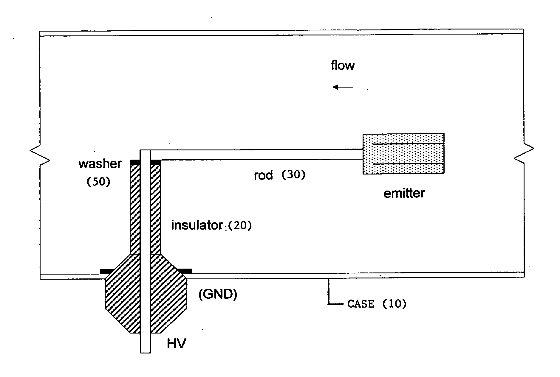
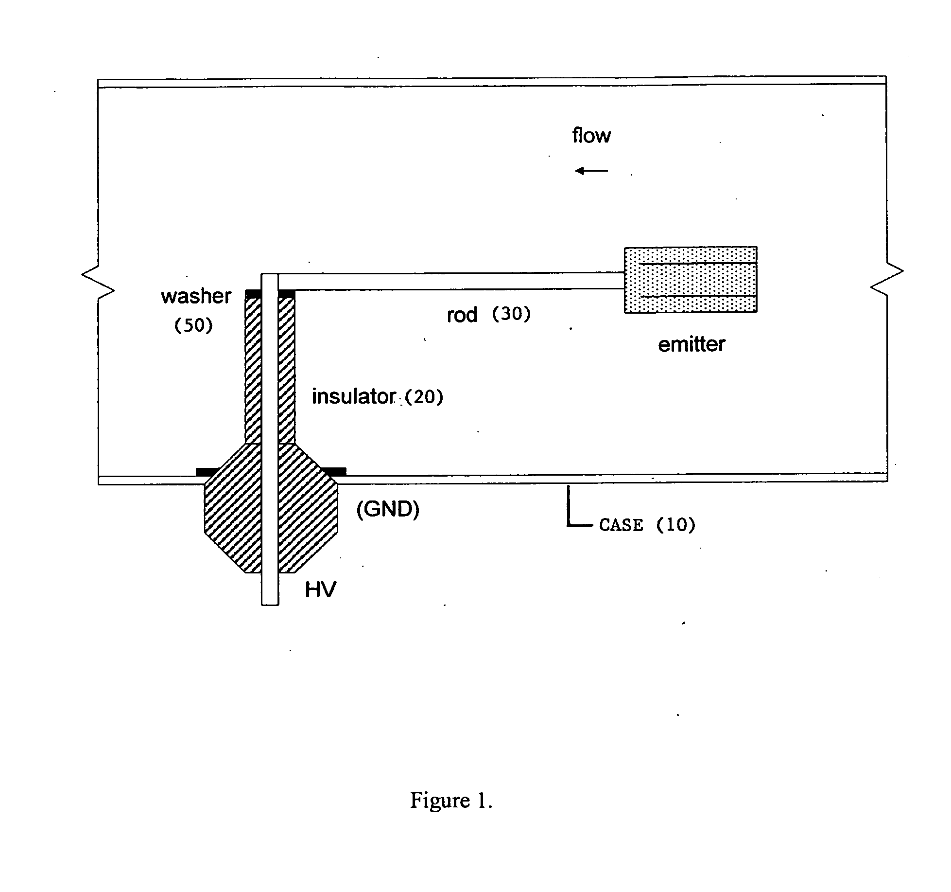
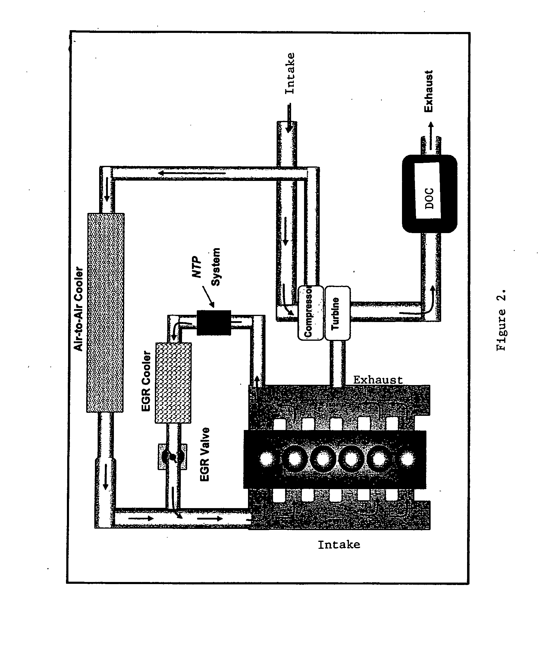
"The present invention provides a system for reducing the amount of particulate matter in a gas stream using non-thermal plasma (NTP) generated by a plasma reactor. The system includes a first conductor, a second conductor, and an insulator electrically isolating the first and second conductors. The insulator is a self-cleaning insulator that reduces buildup of conductive material on its surface, which can cause a reduction in NTP production. The system also includes one or more non-eroding washers and a pulsed direct current applied to the first conductor. The invention also provides methods for reducing particulate matter in a gas stream using the NTP system."

Problems solved by technology

Unfortunately, robust technologies for meeting these standards have been difficult to obtain.
Despite the attractiveness of NTP-based systems for reducing engine emissions, the use of this technology has been complicated by the effects of the pollutants and breakdown products in exhaust gases on these systems.
In this regard, particulate matter is especially problematic, since its accumulation in these systems can cause the physical blockage of narrow gas-flow regions.
Such PM can also degrade or destroy the performance of NTP systems by coating the components involved in the generation of NTP.
In the case of systems where NTP is generated electrically, PM accumulation can cause power losses via the redirection of current into conductive paths created by the accumulation of this conductive material, thereby reducing the amount of NTP generated, and therefore the amount of particulate matter removed.
Another concern is the amount of power consumed to reduce the PM.
Existing NTP systems can consume hundreds of watts of power just to reduce PM by 25%.
Energy used to power the system reduces the power available for other uses and increases the emissions.

Method used


Image

  • Non-thermal plasma particulate removal systems and methods thereof
  • Non-thermal plasma particulate removal systems and methods thereof
  • Non-thermal plasma particulate removal systems and methods thereof

Examples


Embodiment Construction

[0038]The present invention is broadly directed to non-thermal plasma-based systems for reducing the amount of particulate matter (PM) in a gas stream, as well as to methods for using such systems. The present invention is particularly directed to such non-thermal plasma-based particulate matter reduction systems with self-cleaning surfaces. Particularly contemplated are self-cleaning surfaces that reduce particulate matter buildup such as is likely to cause the reduction of non-thermal plasma production in the system, and therefore the ability of such systems to reduce the amount of particulate matter in the gas stream.

[0039]Thus the present invention is broadly directed to NTP-based systems for reducing the amount of particulate matter in a gas stream. “NTP” refers to non-thermal plasma, which has its usual art-defined meaning, as provided in, e.g., the Background section of this application, Yamamoto and Okubo, etc. In the present invention, NTP is preferably electrically generat...


PUM


Abstract

The present invention is broadly directed to non-thermal plasma-based systems for reducing the amount of particulate matter in a gas stream, as well as to methods for using such systems. The present invention is particularly directed to such non-thermal plasma-based particulate matter reduction systems with self-cleaning surfaces. Particularly contemplated are self-cleaning surfaces that reduce particulate matter buildup such as is likely to cause the reduction of non-thermal plasma production in the system, and therefore the ability of such systems to reduce the amount of particulate matter in the gas stream.

Description

RELATED APPLICATIONS[0001]This application claims the benefit of U.S. Provisional Application Nos. 61 / 039,300 and 61 / 039,303, both filed Mar. 25, 2008.FIELD OF THE INVENTION[0002]The present invention is broadly directed to non-thermal plasma-based systems for reducing the amount of particulate matter in a gas stream, as well as to methods for using such systems. The present invention is particularly directed to such non-thermal plasma-based particulate matter reduction systems with self-cleaning surfaces. Particularly contemplated are self-cleaning surfaces that reduce particulate matter buildup such as is likely to cause the reduction of non-thermal plasma production in the system, and therefore the ability of such systems to reduce the amount of particulate matter in the gas stream.BACKGROUND OF THE INVENTION[0003]Internal combustion engines fueled by gasoline or diesel, either alone or in combination with other compounds (e.g., ethanol), are sources of large amounts of air and o...

Claims


Application Information

Patent Timeline
Patent Type & Authority Applications(United States)
IPC IPC(8): B03C3/74
CPCF01N3/38Y02T10/20H05H1/24F01N2240/28Y10S55/30Y10S55/10H05H1/2406H05H2240/20Y02T10/12
Inventor OGUT, ALIBACKUS, RICHARD
Owner ENVIRONMENTAL ENERGY TECH
Learn More