Burner for a heater device with improved fuel supply

a heater and burner technology, applied in the direction of burners, combustion types, combustion processes, etc., can solve the problem that the essentially unatomized fuel jet cannot reach the starting zone, and achieve the effect of reliable and low-emission starting behavior and less dense smok

Inactive Publication Date: 2009-09-24
WEBASTO AG
View PDF19 Cites 0 Cited by
  • Summary
  • Abstract
  • Description
  • Claims
  • Application Information

AI Technical Summary

Benefits of technology

[0009]The object of the invention is to overcome the described problems of the prior art at least in part and especially to enable reliable and low-emission starting behavior with little dense smoke in different installation positions.

Problems solved by technology

In particular, for a small primary air amount, for which the supplied primary air should have only little angular momentum, an essentially unatomized fuel jet can reach the starting zone.

Method used


Image

  • Burner for a heater device with improved fuel supply
  • Burner for a heater device with improved fuel supply
  • Burner for a heater device with improved fuel supply

Examples


Embodiment Construction

[0031]In the following description of preferred embodiments of the invention, the same reference numbers label the same or comparable components.

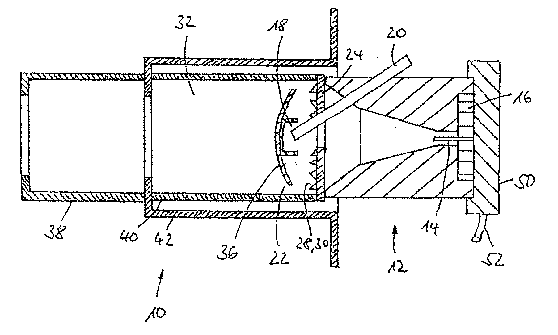
[0032]FIG. 1 shows a sectional view of the burner in accordance with the invention. The burner 10 in accordance with the invention has a nozzle 12 which is securely joined to the heat shield 24. The heat shield 24 together with a burner tube 40 which is connected to the heat shield 24 defines a combustion chamber 22. The combustion chamber tube 40 is surrounded by an outer pipe 42 which forms the burner flange. A flame tube 38 is attached to this outer pipe 42. The connections between the heat shield 24 and the combustion chamber tube 40 or between the combustion chamber tube 40, the outer pipe 42 and the flame tube 38 are generally welded connections. On the fuel nozzle 12, there is a fuel supply 50 which has a metal pipe 52 for supplying of fuel and a fuel needle 14 for injection of fuel into the combustion chamber 22. Furthermore, in the...


PUM


Abstract

A burner for a heater, especially for use in motor vehicles, with a burner nozzle (12) for supplying and atomizing of fuel, which has a fuel needle (14) for supplying fuel to the burner (10) and a combustion air supply (16) for supplying combustion air to the burner, and a starting zone (18) in which ignition of the fuel to start the burner takes place. It is provided that, by choosing the inside diameter of the fuel needle (14) the exit speed of the fuel is predetermined such that, during the starting phase of the burner (10), fuel in essentially unatomized form reaches the starting zone (18).

Description

BACKGROUND OF THE INVENTION[0001]1. Field of Invention[0002]The invention relates to a burner for a heater, especially for use in motor vehicles, with a burner nozzle for supply and atomization of fuel, which has a fuel needle for supplying fuel to the burner and a combustion air supply for supplying combustion air to the burner, and a starting zone in which ignition of the fuel to start the burner takes place.[0003]2. Description of Related Art[0004]Burners of the initially mentioned type, which are also called atomization burners or spray burners, are used especially in auxiliary heaters and engine independent heaters for motor vehicles.[0005]There are numerous requirements for these burners, especially with respect to reliable and largely emission-free starting behavior and stable combustion operation. Furthermore, an effort is made to build heaters which can be used in different installation positions.[0006]With respect to starting behavior, various operating parameters must be ...

Claims


Application Information

Patent Timeline
Patent Type & Authority Applications(United States)
IPC IPC(8): F23M9/06
CPCF23D9/00F23D11/24F23D2900/11401F23D11/408F23D11/406F23D11/40
Inventor POHNER, MICHAELWIDEMANN, FRIEDRICHWEBER, STEFFENSTEFFENS, JAN
Owner WEBASTO AG
Why Eureka
Try Eureka