
Mass spectrometer

a mass spectrometer and mass spectrometer technology, applied in the field of mass spectrometers, can solve problems such as reducing analytical efficiency, and achieve the effects of reducing the number of parts, reducing the number of control circuit design and parts, and reducing the number of parameter setting items for users

Active Publication Date: 2009-09-24
SHIMADZU CORP
View PDF2 Cites 17 Cited by
  • Summary
  • Abstract
  • Description
  • Claims
  • Application Information

AI Technical Summary

Benefits of technology

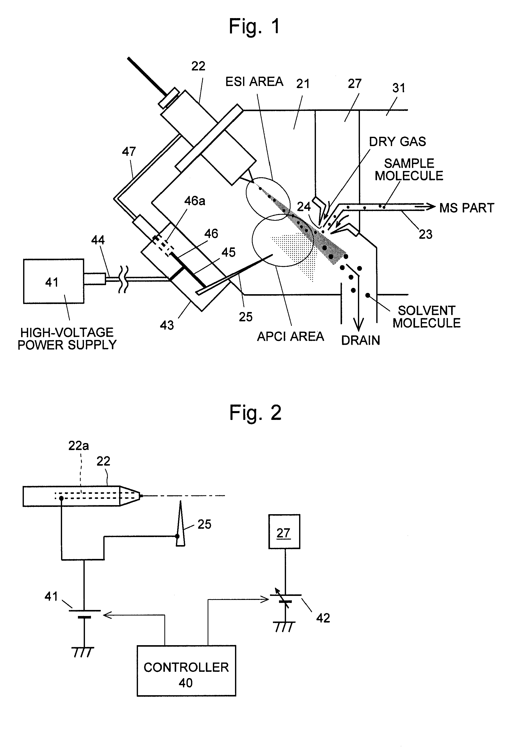
[0021]Since the LC / MS according to the present invention as described earlier simultaneously applies the same voltage to both the electrostatic spray and the corona discharger, the labor for a control circuit design and the number of parts are reduced, which leads to a lower production cost. Another advantage is that parameter setting items for the user are reduced, which simplifies the operation. Such mass spectrometer according to the present invention simultaneously performs ionizations according to ESI and APCI; hence, it can be preferably used for a high-throughput analysis intended for diverse samples.
[0022]In the case where the mass spectrometer includes the bifurcator as previously described, the voltage supplier can be configured by connecting a feeder cable leading out of the bifurcator to a high-voltage power supply and simultaneously connecting a feeder cable leading out of the electrostatic spray to a feeder port placed in the bifurcator. This brings about the advantage that an existing ESI probe can be used without modification.

Problems solved by technology

Since such changing operation causes much trouble, however, this is one of the reasons to decrease the analytical efficiency.

Method used


Image

  • Mass spectrometer
  • Mass spectrometer
  • Mass spectrometer

Examples


Embodiment Construction

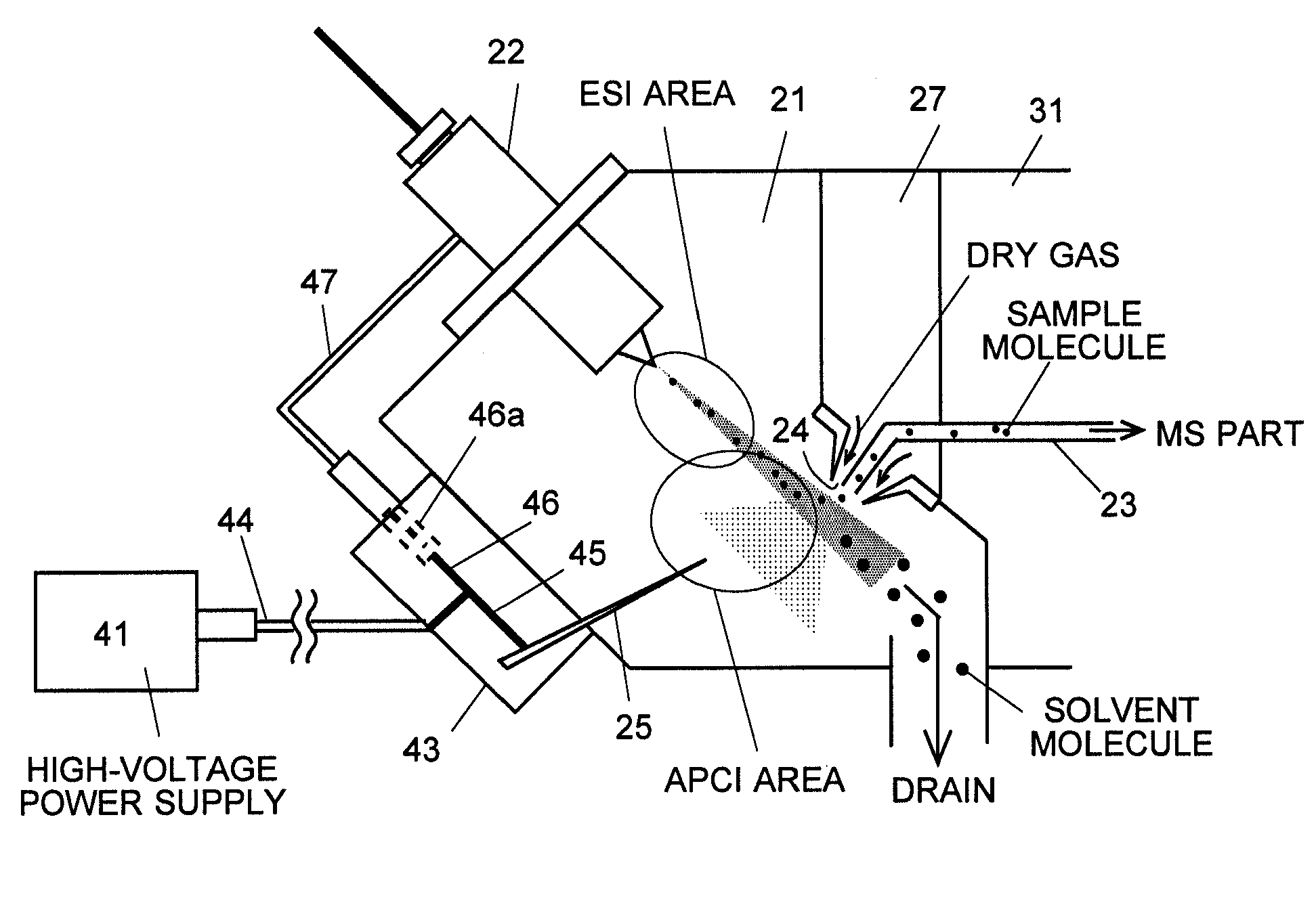
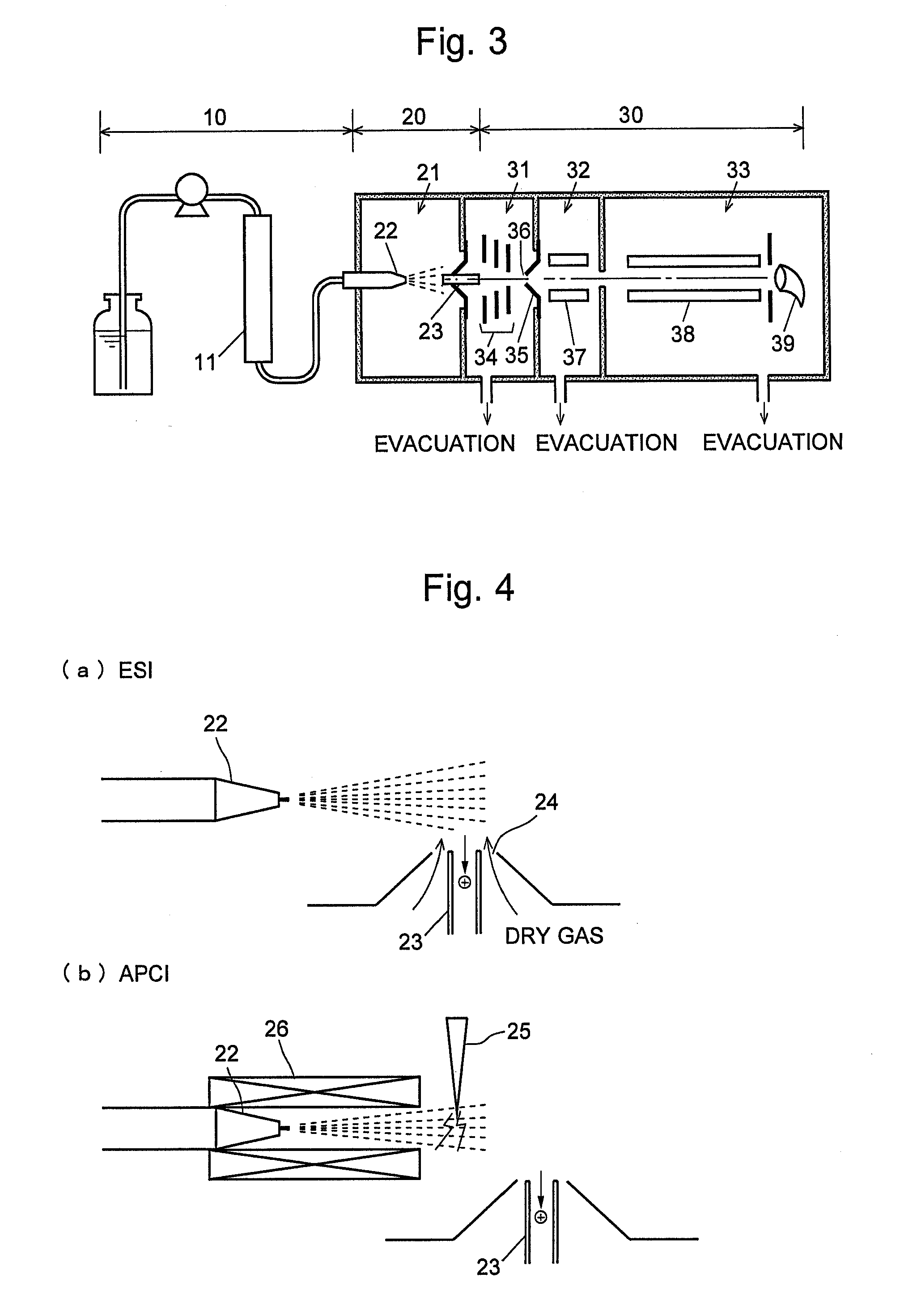
[0057]Hereinafter, one embodiment of the atmospheric pressure ionization mass spectrometer according to the present invention will be explained with reference to the figures. FIG. 1 is a schematic configuration diagram of an ionization interface section of the atmospheric pressure ionization mass spectrometer according to the present embodiment. FIG. 2 is an electric schematic configuration diagram of the main portion of the mass spectrometer. The explanation for the basic configuration other than those aforementioned is omitted because it is similar to that of a conventional general MS which was explained with respect to FIG. 3.

[0058]As illustrated in FIG. 1, a spray nozzle 22 as an electrostatic spray and a needle-like discharging electrode 25 as a corona discharger are placed in an ionization interface section. These are placed in the position so that the optimum application voltage to both the electrostatic spray and the discharging electrode becomes identical. At the boundary o...


PUM


Abstract

In a liquid chromatograph mass spectrometer having an ionization interface capable of simultaneously performing ionization operations by ESI and APCI, a spray nozzle 22 for spraying a liquid sample given form a liquid chromatograph section as charged droplets, and a corona discharger 25 for ionizing mobile phase solvent molecules are placed in the same ionization chamber 21. The same voltages are applied to both the spray nozzle and the corona discharger from a single high-voltage power supply 41. The electrical power's value of the heater 27 of the heated dry gas supplier for drying the charged droplets generated in the spray nozzle 22 are set to be suitable for the ionization according to APCI. Consequently, the labor for the circuit design and the number of the parts are reduced. At the same time, the parameter setting items for the user are decreased, which leads to enhanced operability.

Description

TECHNICAL FIELD[0001]The present invention relates to a mass spectrometer, and in particular to an ionization interface for ionizing a liquid sample supplied from a liquid chromatograph or other devices and then introducing it to a mass spectrometer section.BACKGROUND ART[0002]FIG. 3 is a schematic configuration diagram illustrating one example of a conventionally-known general liquid chromatograph mass spectrometer (LC / MS). A sample liquid temporally separated and eluted from a column 11 of a liquid chromatograph section (LC section) 10 is introduced into an interface section (atmospheric pressure ionization interface) 20, and is then sprayed from a spray nozzle 22 into an ionization chamber 21 to be ionized. Fine droplets including ions generated go inside a tubule (desolvation tube) 23 placed ahead and are sent to a mass analysis section (MS section) 30. The desolvation tube 23 is warmed by a heater (which is not shown) and the evaporation of the solvent in the droplets progresse...

Claims


Application Information

Patent Timeline
Patent Type & Authority Applications(United States)
IPC IPC(8): H01J49/00
CPCG01N30/726H01J49/168H01J49/165G01N30/7266
Inventor KOBAYASHI, MASATO
Owner SHIMADZU CORP
Learn More