
Optical signal synchronization sampling apparatus and method, and optical signal monitoring apparatus and method using the same

a sampling apparatus and optical signal technology, applied in the field of optical signal synchronization sampling apparatus and method, can solve the problems of insufficient resolution, inability to accurately obtain information on the waveform of optical signal modulated at tens of gb/s, and difficulty in obtaining waveform information by photodetector, etc., to achieve high sampling efficiency, accurate sampling, and sufficient resolution

Inactive Publication Date: 2009-09-17
ANRITSU CORP
View PDF6 Cites 6 Cited by
  • Summary
  • Abstract
  • Description
  • Claims
  • Application Information

AI Technical Summary

Benefits of technology

[0018]In order to solve the problems of the conventional technique, an object of the invention is to provide optical signal synchronization sampling apparatus and method, in which the information on the waveform of the high-speed optical signal can accurately be sampled with the high sampling efficiency and sufficient resolution, and optical signal monitoring apparatus and method, in which the eye pattern of the optical signal can stably be obtained while the optical signal can correctly be monitored using the optical signal synchronization sampling apparatus and method.
[0027]In order to achieve the above-described object, according to a second aspect of the present invention, there is provided the optical signal synchronization sampling apparatus according to the first aspect, wherein, in order to prevent leakage of the sampling optical pulse (Ps) to a transmission path of the sampling object optical signal (Px), the sampling optical pulse (Ps) being input into the other of the two optical terminals (23a, 23b) of the electroabsorption optical modulator (23),
[0052]In order to achieve the above-described object, according to a sixth aspect of the present invention, there is provided the optical signal monitoring apparatus according to the fifth aspect, wherein, in order to prevent leakage of the sampling optical pulse (Ps) to a transmission path of the monitoring object optical signal (Px), the sampling optical pulse (Ps) being input into the other of the two optical terminals (23a, 23b) of the electroabsorption optical modulator (23),
[0117]Therefore, the optical pulse having the narrow width can be used as the sampling optical pulse, the loss can be decreased for the sampling object optical signal, the sampling efficiency can substantially be enhanced, and the synchronization sampling of the information on the waveform of the sampling object optical signal can accurately be performed with the sufficient resolution even if the sampling object optical signal is a weak optical signal.
[0119]Therefore, the optical pulse having the narrow width can be used as the sampling optical pulse, the loss can be decreased for the monitoring object optical signal, the sampling efficiency can substantially be enhanced, and the information on the waveform of the monitoring object optical signal can accurately be obtained with the sufficient resolution even if the monitoring object optical signal is a weak optical signal.

Problems solved by technology

Therefore, in the optical signal monitoring apparatus, it is extremely difficult to obtain the waveform information by a photodetector directly receiving the optical signal which is modulated by a data signal having a bit rate very high as tens of Gb / s.
However, in the technique disclosed in Patent Document 2, high-frequency impedance matching is required in the electric sampling pulse signal, and it is extremely difficult that a pulse width of the electric sampling pulse signal is stably narrowed without ringing.
Therefore, there is generated a new problem in that the information on the waveform of the optical signal modulated at tens of Gb / s cannot accurately be obtained with sufficient resolution.
In the case where the quality computation processing is performed to the eye pattern, a temporal axes of the superimposed waveforms are gradually shifted unless the sampling period Ts is strictly matched with N·Tc+ΔT, which results in another problem in that the quality computation cannot correctly be performed.

Method used


Image

  • Optical signal synchronization sampling apparatus and method, and optical signal monitoring apparatus and method using the same
  • Optical signal synchronization sampling apparatus and method, and optical signal monitoring apparatus and method using the same
  • Optical signal synchronization sampling apparatus and method, and optical signal monitoring apparatus and method using the same

Examples


Embodiment Construction

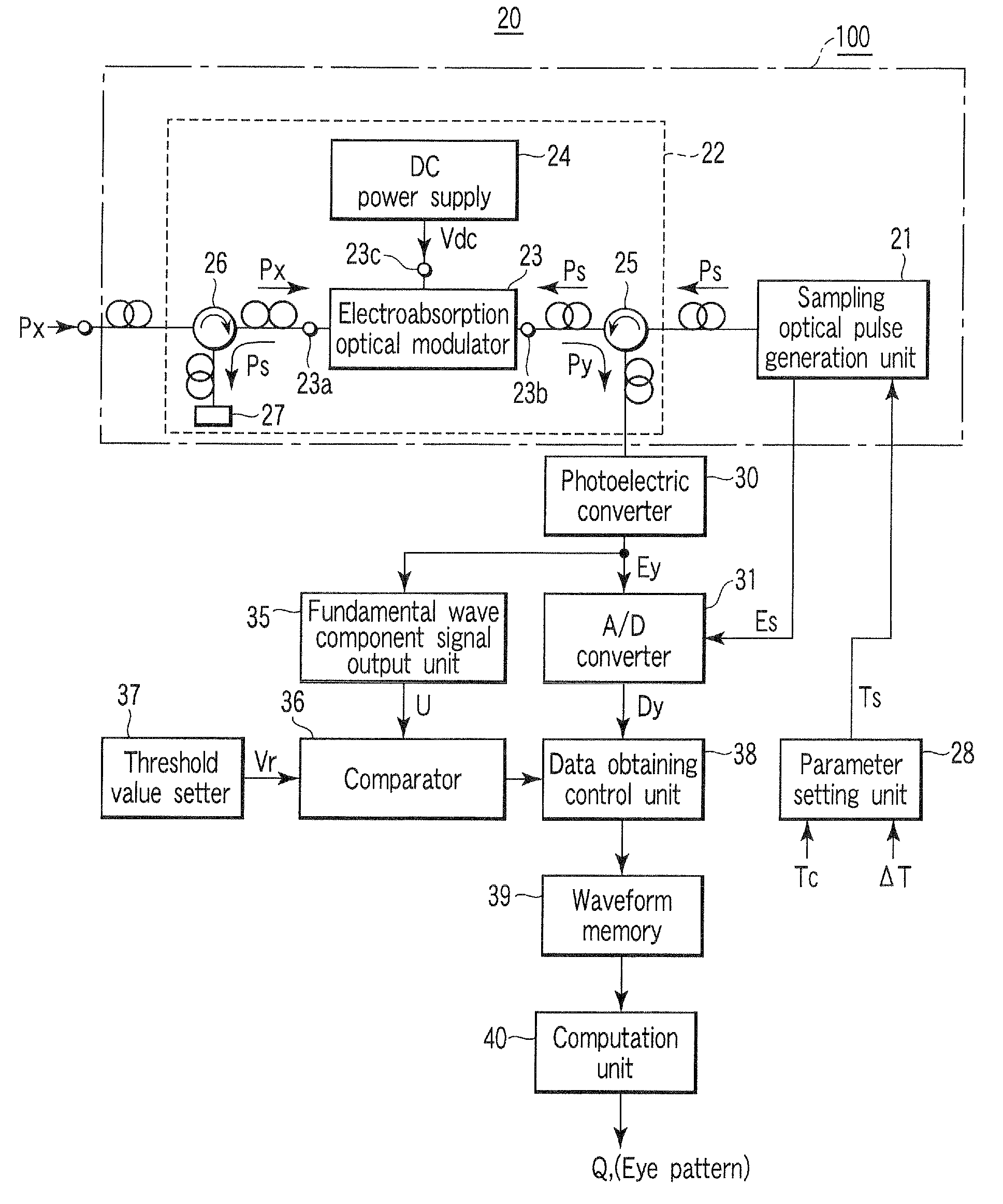
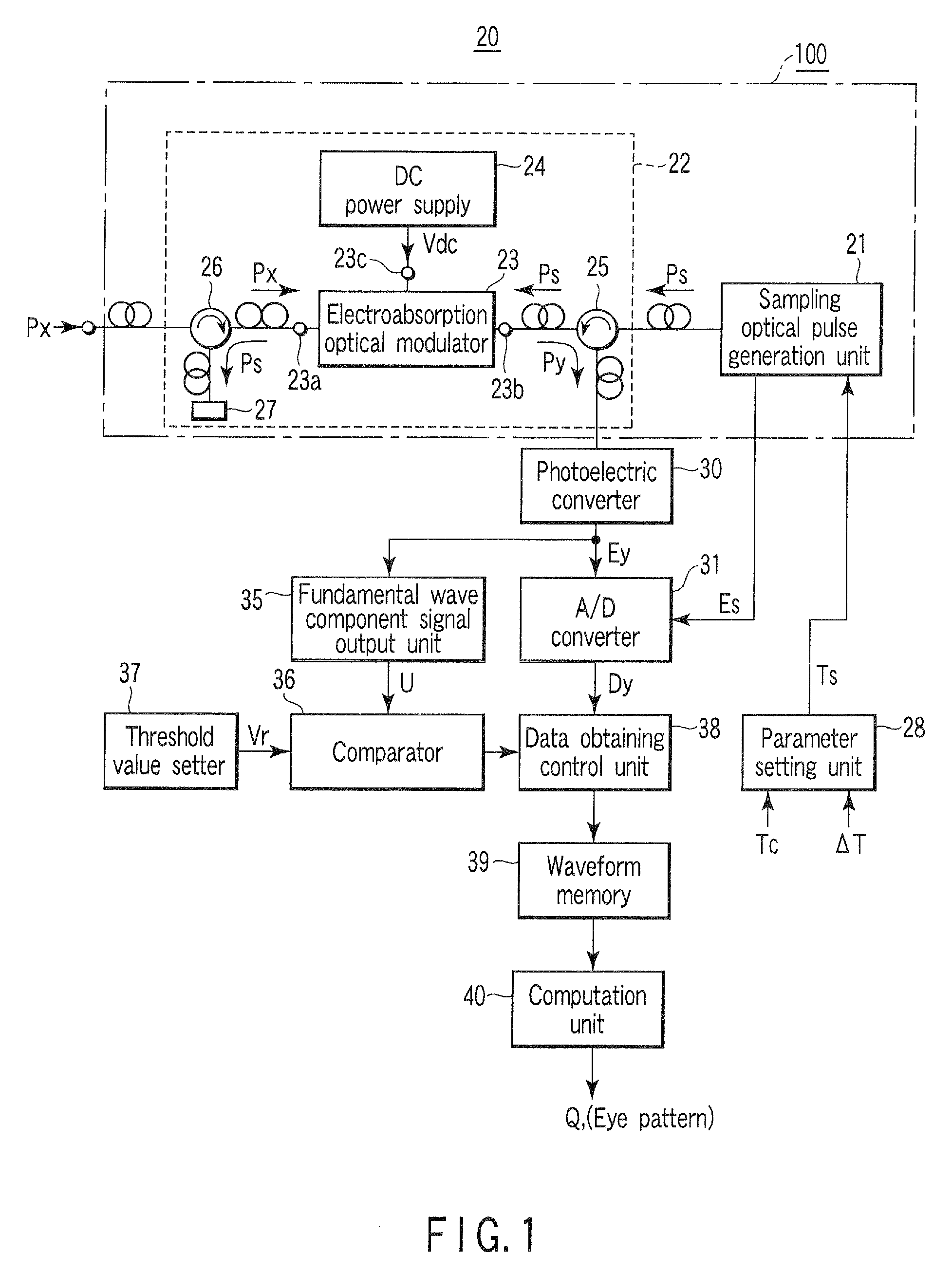
[0130]A first embodiment, to which an optical signal synchronization sampling apparatus and an optical signal monitoring apparatus in which the optical signal synchronization sampling apparatus is used are applied, will be described with reference to the accompanying drawings.

[0131]FIG. 1 is a block diagram showing a configuration of the first embodiment of an optical signal synchronization sampling apparatus 100 according to the invention and an optical signal monitoring apparatus 20 using the optical signal synchronization sampling apparatus 100.

[0132]A basic configuration of the optical signal synchronization sampling apparatus 100 according to the invention includes a sampling optical pulse generation unit 21 which emits a sampling optical pulse Ps having a period Ts different from a predetermined offset time ΔT to N integral multiplications of a clock period Tc of a data signal, the data signal modulating a sampling object optical signal Px; and an optical sampling unit 22 whic...


PUM


Abstract

An electroabsorption optical modulator used as a sampling element has two optical terminals and a power supply terminal, the two optical terminals are used to input and output light, and the power supply terminal imparts an electric field to an optical path connecting the two optical terminals. The electroabsorption optical modulator has a characteristic in which an absorption index is changed with respect to the light beam propagating through the optical path according to a level of the electric field. A monitoring (synchronization sampling) object optical signal is input into one of the two optical terminals of the electroabsorption optical modulator. A predetermined direct-current voltage exhibiting a high absorption index for the monitoring (synchronization sampling) object optical signal is imparted to the power supply terminal of the electroabsorption optical modulator. A sampling optical pulse is input into another of the two optical terminals of the electroabsorption optical modulator through a photocoupler. The absorption index for the monitoring (synchronization sampling) object optical signal is lowered by a mutual absorption saturation characteristic of the electroabsorption optical modulator, and synchronization sampling of the monitoring (synchronization sampling) object optical signal is performed to supply an optical signal from the other of the two optical terminals of the electroabsorption optical modulator through the photocoupler. The mutual absorption saturation characteristic is generated when the sampling optical pulse is input into the other of the two optical terminals.

Description

TECHNICAL FIELD[0001]The present invention relates to optical signal synchronization sampling apparatus and method and optical signal monitoring apparatus and method using the same, and particularly to optical signal synchronization sampling apparatus and method in which a technique of enabling information on a waveform of an optical signal modulated by a high-speed data signal to be accurately sampled with sufficient resolution is adopted, and optical signal monitoring apparatus and method in which the optical signal can correctly be monitored using the optical signal synchronization sampling apparatus and method.BACKGROUND ART[0002]In forming a network using the optical signal modulated by the data signal, it is necessary to monitor the quality of the optical signal propagating through the network with the optical signal monitoring apparatus.[0003]Generally, the optical signal monitoring apparatus obtains information on a waveform of a signal on a transmission path, and computes a...

Claims


Application Information

Patent Timeline
Patent Type & Authority Applications(United States)
IPC IPC(8): H04B10/00H04B10/07H04B10/079
CPCG01J11/00G02F2001/0157G02F1/091G02F1/0121G02F1/0157
Inventor OTANI, AKIHITOTANIMOTO, TAKAO
Owner ANRITSU CORP
Learn More