Magnetron

a magnetic circuit and magnet ring technology, applied in the field of magnets, can solve the problems of inability to achieve desired oscillation efficiency, difficulty in positioning the magnet ring, and limit in improving so as to improve the efficiency of the magnetic circuit, and stabilize the magnetic field distribution in the active field

Active Publication Date: 2009-09-03
PANASONIC CORP
View PDF6 Cites 1 Cited by
  • Summary
  • Abstract
  • Description
  • Claims
  • Application Information

AI Technical Summary

Benefits of technology

[0006]The invention is made in view of the aforesaid circumstances and an object of the invention is to provide a magnetron which can conduct more magnetic flux in the active space at the periphery of a cathode structure to thereby further improve the efficiency of a magnetic circuit.
[0009]According to this configuration, the thickness of the magnet ring from the position corresponding to the outer diameter position of the anode cylinder to the position corresponding to the outer diameter position of the circular magnet differs from the thickness of the remaining part of the magnet ring. Thus, unlike the related art, there is no fear that the cut and erected part or the projection portions obstructs the flow of the magnetic flux lines, and so the more magnetic flux can be flown in the active space at the periphery of the cathode structure, whereby the efficiency of the magnetic circuit can be improved. Further, unlike the related art, the invention does not employ the structure that the seal flange of a large diameter is coupled to the opening portion of the anode cylinder and the magnet ring is joined to the seal flange, but the invention employs the structure that the anode cylinder is disposed separately from the magnet ring, whereby the assembling procedure can be performed easily.
[0013]In addition, the magnet ring is configured in a manner that the magnetic ring includes a plurality of bended parts directed to the anode cylinder and a plurality of plane parts at the outer periphery of the magnetic ring. The bended parts and the plane parts are periodically and alternately arranged. Thus, both the increase of a flowing amount of the magnetic flux in the active space at the periphery of the cathode structure and the positioning of the anode cylinder and the magnet ring can be achieved simultaneously. That is, the improvement of the efficiency of the magnetic circuit and the stabilization of the magnetic field distribution in the active space can be achieved simultaneously.
[0015]According to this configuration, the projection portion is provided between the first and the second position. Thus, unlike the related art, there is no fear that the cut and erected part or the projection portions provided at the outer circumferential end of the magnet ring obstructs the flow of the magnetic flux lines. As a result, since more magnetic flux can be flown in the active space at the periphery of the cathode structure, the efficiency of the magnetic circuit can be improved.
[0021]The performance can be further improved when the magnetron is applied to a device utilizing a microwave such as a microwave oven.
[0022]According to the magnetron of the invention, the improvement of the efficiency of the magnetic circuit and the stabilization of the magnetic field distribution in the active space can be achieved.

Problems solved by technology

However, since the magnet ring of the magnetron of the related art has a uniform thickness, the magnetic flux is also attracted on the outer periphery side which does not so much contribute to the conduction of the magnetic flux in the active space at the periphery of the cathode structure, so that there is a limit in the improvement of the efficiency of the magnetic circuit.
Thus, the positioning of the magnet ring is difficult in the manufacturing process of the magnetron.
Thus, there arises a problem that the oscillation becomes unstable and desired oscillation efficiency can not be achieved.
There arises a problem that the cut and erected part or the projection portions obstructs the flow of the magnetic flux lines to thereby degrade the efficiency of the magnetic circuit.

Method used


Image

  • Magnetron
  • Magnetron
  • Magnetron

Examples


Embodiment Construction

[0045]Hereinafter, a preferred embodiment of the invention will be explained in detail with reference to drawings.

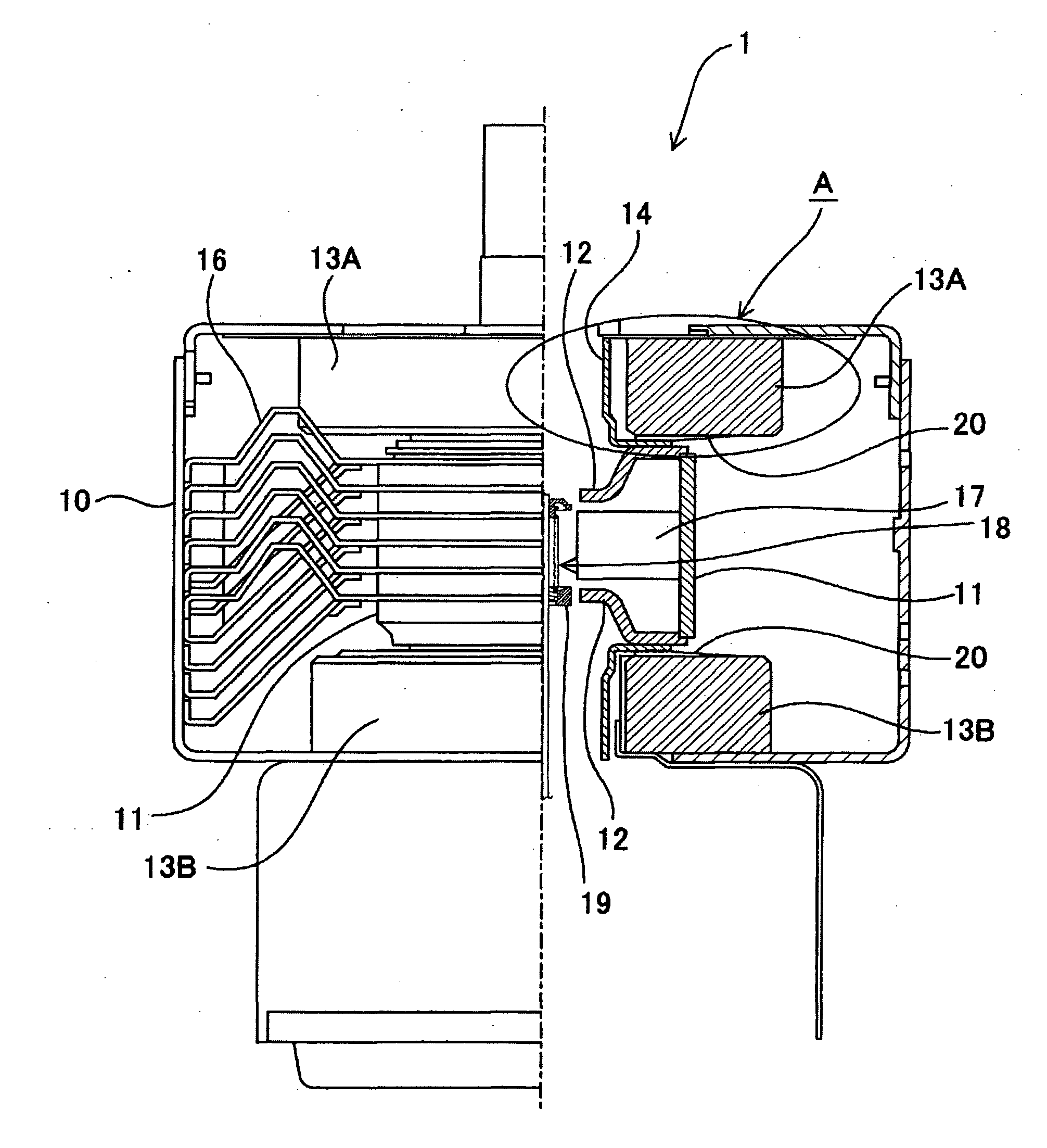
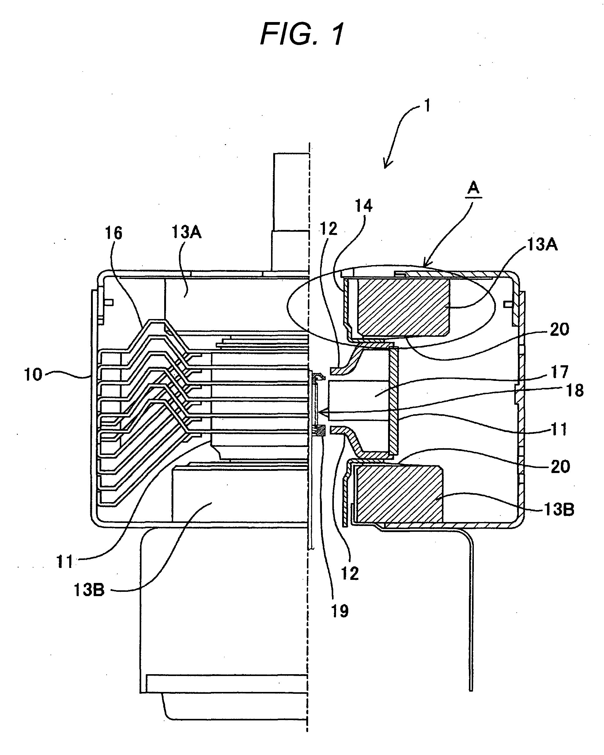
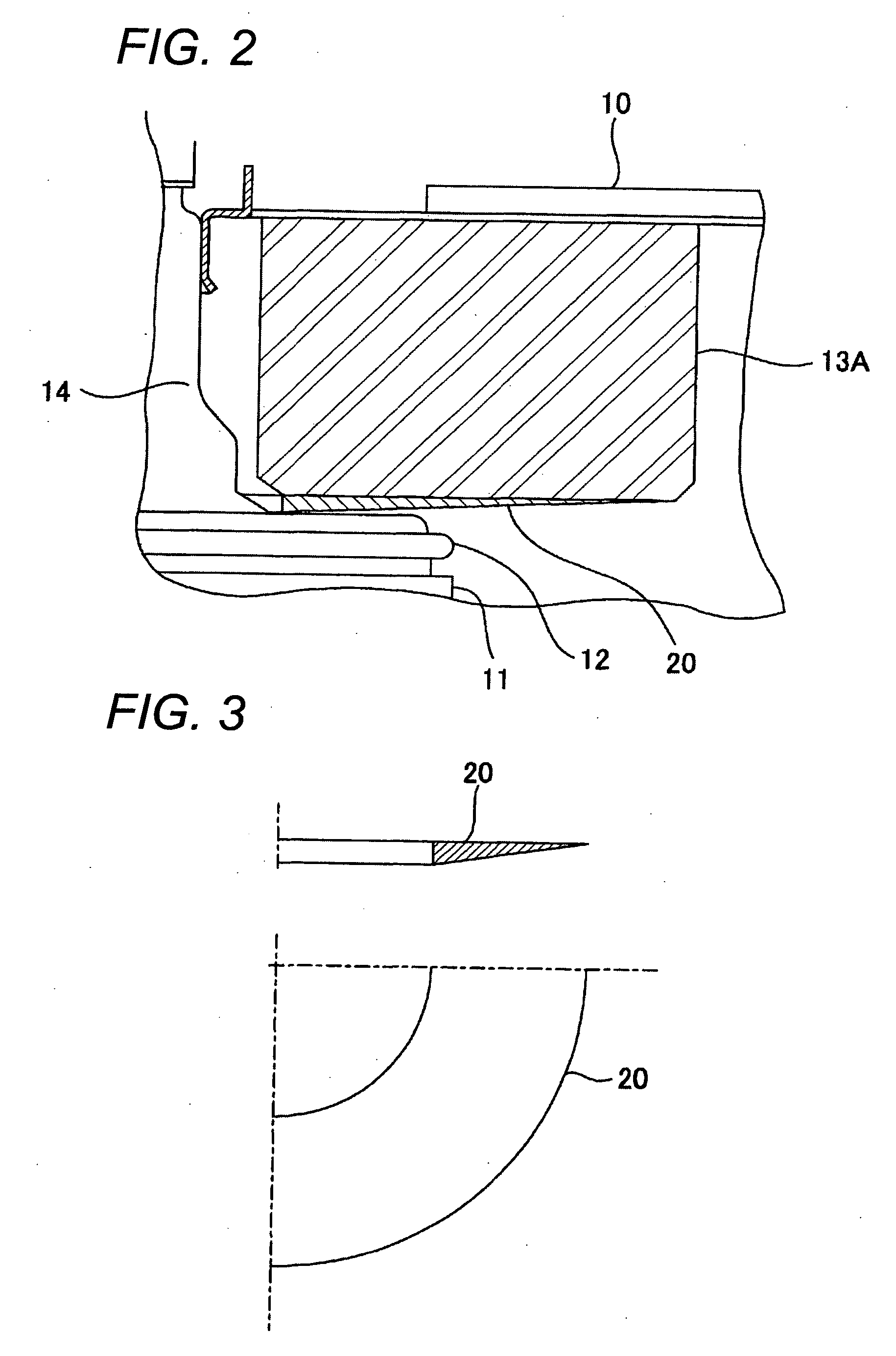
[0046]FIG. 1 is a partially cutaway view of the magnetron according to the embodiment of the invention and shows an anode cylinder, circular magnets, cooling fins and so on within a magnetic yoke. FIG. 2 is an enlarged diagram of the portion A of the magnetron 1 shown in FIG. 1. In FIGS. 1 and 2, within the magnetic yoke 10, there are disposed the anode cylinder 11 having pole pieces 12 respectively fixed at opening ends on the both sides thereof, the doughnut-shaped circular magnets 13A, 13B respectively disposed just above the upper part and just below the lower part of the anode cylinder 11, and a side tube 14 on the anode side. Further, magnet rings 20 are disposed between a part of the upper portion of the side tube 14 and the circular magnet 13A and between a part of the lower portion of the side tube 14 and the circular magnet 13B, respectively.

[0047]Cooling fins ...


PUM


Abstract

The present invention provides a magnetron which can conduct more magnetic flux in the active space at the periphery of a cathode structure to thereby further improve the efficiency of a magnetic circuit. The magnetron of the present invention includes an anode cylinder on which inner wall a plurality of anode vanes are provided, a pole piece provided on an end side of the anode cylinder, a circular magnet provided on the vicinity of the pole piece, and a magnet ring provided between the anode cylinder and the circular magnet. An outer diameter of the magnet ring is smaller than or equal to the outer diameter of the circular magnet and larger than or equal to the outer diameter of the anode cylinder. The magnet ring has a portion on a surface of the pole piece side whose normal line is non-parallel to the central axis of the anode cylinder.

Description

BACKGROUND OF THE INVENTION[0001]The present invention relates to a magnetron used for a device utilizing a microwave such as a microwave oven.[0002]The aforesaid magnetron is configured in a manner, as an example, that a magnet ring (also called as a conversion plate or a shim plate) formed by magnetic material is disposed between an anode cylinder having anode vanes disposed radially on the inner wall surface thereof and an circular magnet disposed on the opening end side of the anode cylinder, in order to improve a magnetic force in an active space at the periphery of a cathode structure (refer JP-A-2002-163993, for example). Since the magnet ring is disposed, much magnetic flux can be conducted into the active space, so that the efficiency of a magnetic circuit can be improved.[0003]In order to improve the efficiency of the magnetic circuit, it is important to conduct much magnetic flux in the active space at the periphery of the cathode structure. However, since the magnet ring...

Claims


Application Information

Patent Timeline
Patent Type & Authority Applications(United States)
IPC IPC(8): H01J25/587
CPCH01J25/587H01J23/10
Inventor KUMAKURA, AYAKOKUWAHARA, NAGISASAITOU, ETSUO
Owner PANASONIC CORP
Why Eureka
Try Eureka