Vehicle with loading boxes or loading surfaces

a technology for loading boxes and vehicles, applied in the direction of monocoque constructions, bottle transportation, transportation items, etc., can solve the problems of additional risk of accidents, traffic obstruction, and position, and achieve the effect of saving maneuvering spa

Active Publication Date: 2009-08-20
HURLER WALTER
View PDF21 Cites 11 Cited by
  • Summary
  • Abstract
  • Description
  • Claims
  • Application Information

AI Technical Summary

Benefits of technology

[0008]The object of the present invention is thus, in the case of a vehicle of the aforementioned nature, in conjunction with which the facility for significantly easier loading and unloading is created by means of the loading boxes or the loading surfaces that are capable of being lowered, additionally to improve these even further, and in particular to create a means of loading and unloading which saves maneuvering space.
[0015]In an embodiment of this kind, in the lowered state or even in intermediate positions, or with the at least one rear loading box or loading surface at ramp height, this is accessible from all three sides, namely from the rear and from both sides, without the need for inconvenient retaining limbs or stabilizing devices.
[0022]In addition to facilitating assembly in this way, and to the advantages associated with prefabrication, this embodiment also offers the advantage that, in the case of repairs or in the event of an accident, the vehicle and the vehicle superstructure can be replaced in a simple fashion.

Problems solved by technology

A disadvantage associated with this process, however, is the need for a correspondingly large maneuvering distance or space behind the vehicle for lowering the loading ramp, which often leads to problems due to a lack of available parking space.
Moreover, the loading ramp in its raised, horizontal position not only constitutes a traffic obstruction, but also represents a source of danger, in particular to the riders of motorcycles and bicycles.
Since, with the loading ramp in its upper raised position, the ramp is situated at a height of more than 1 m (3.28 ft), an additional risk of accident exists in conjunction with loading and unloading, especially if the loading ramp is made slippery by snow or rain.

Method used


Image

  • Vehicle with loading boxes or loading surfaces
  • Vehicle with loading boxes or loading surfaces
  • Vehicle with loading boxes or loading surfaces

Examples


Embodiment Construction

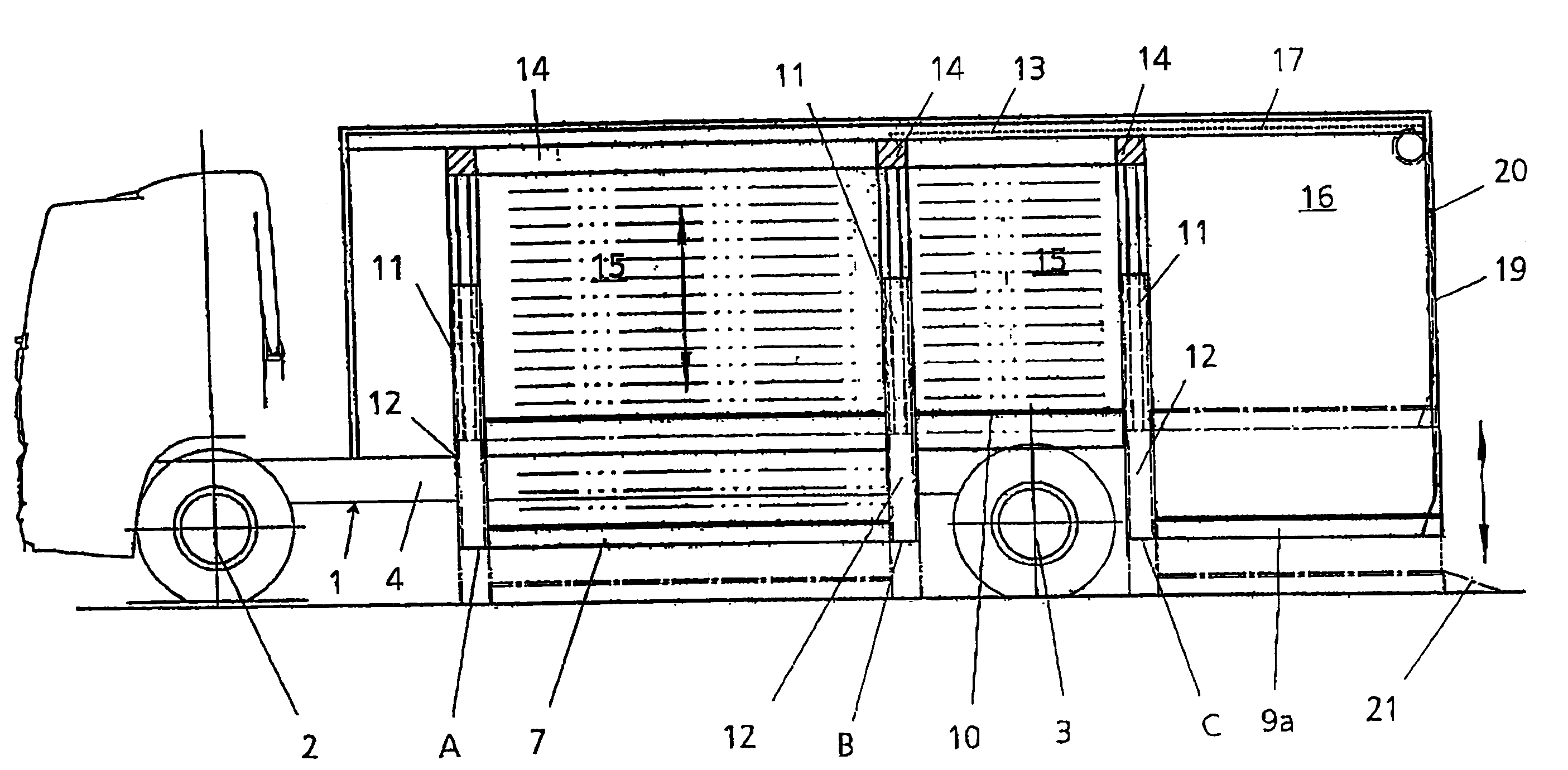
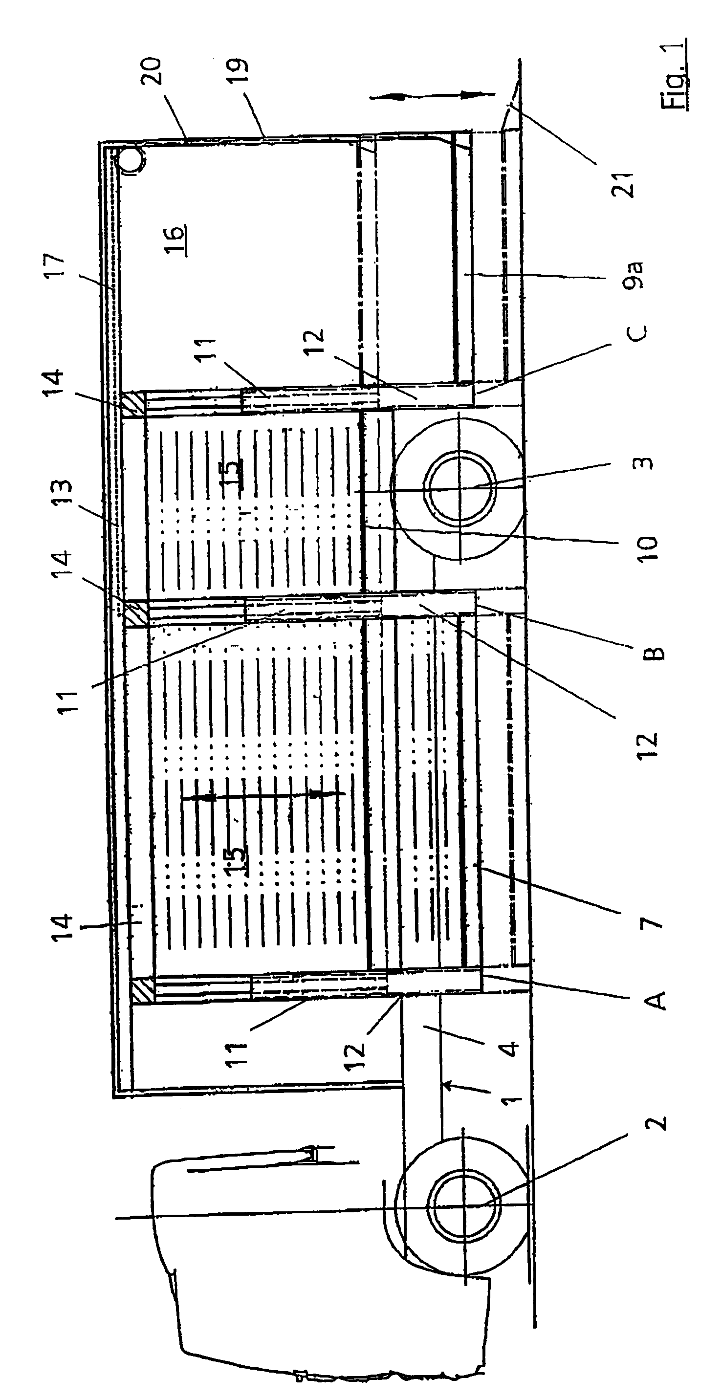
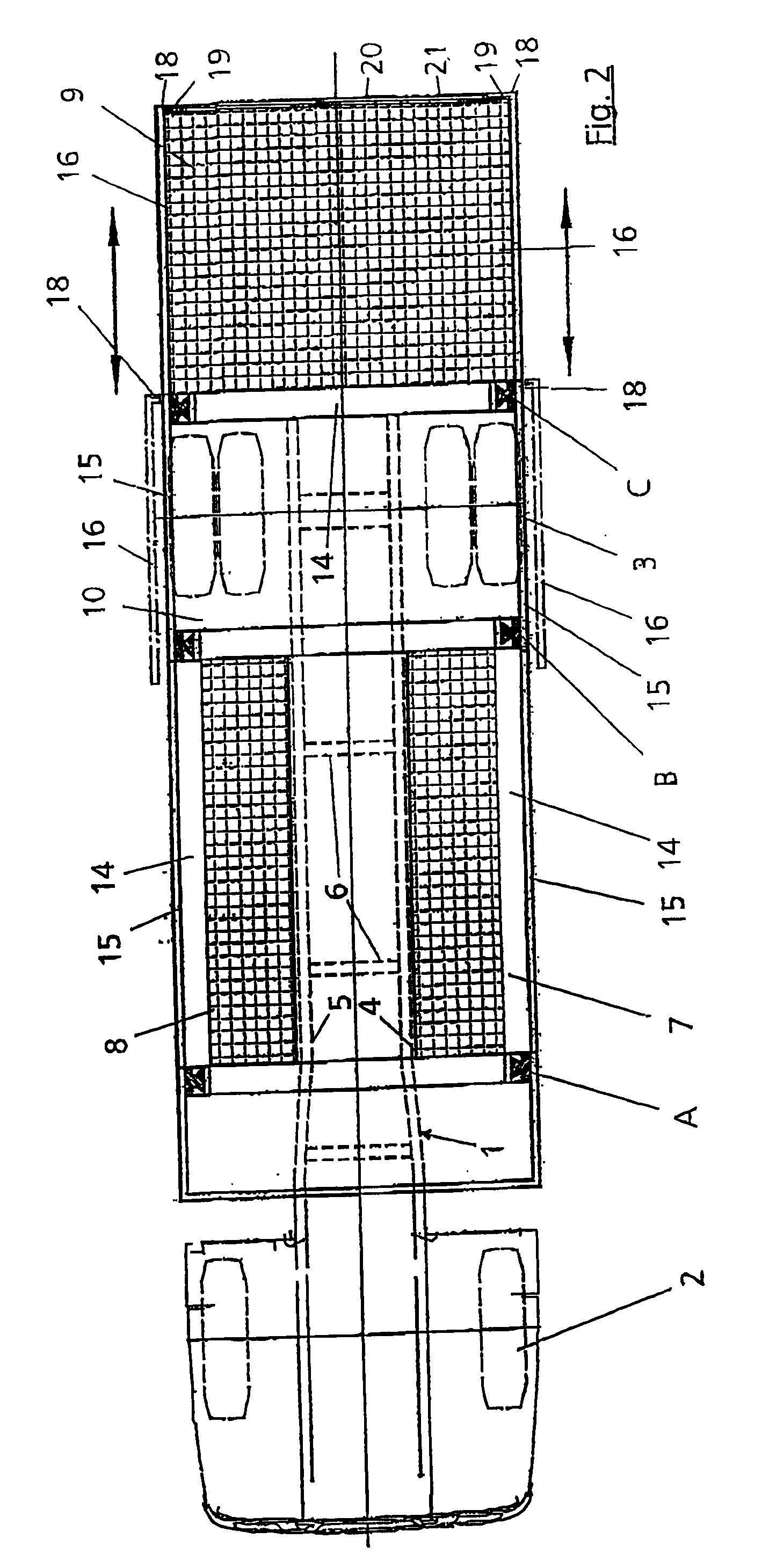
[0031]A vehicle with a vehicle frame 1 as represented in FIGS. 1 to 3 generally exhibits a front axle 2 and a rear axle 3. Of course, more than one front axle 2 or rear axle 3 may be provided in each case. A total of two loading boxes or loading surfaces 7 and 8 that are capable of adjustment in a vertical direction are provided on the vehicle frame 1, which is equipped with a ladder frame having two longitudinal members 4 and 5 running at a distance from one another in the longitudinal direction, and with interjacent transverse members 6, which boxes or surfaces are situated on both sides of the longitudinal members 4 and 5 of the ladder frame and adjacent to it. A third loading box or loading surface 9 that is capable of adjustment in a vertical direction is present behind the rear axle 3. The third loading box 9 can extend over the entire width of the vehicle.

[0032]Present above the rear axle 3 is a further loading box 10, although this is not capable of vertical adjustment.

[0033...


PUM


Abstract

A vehicle provided with at least one front axis and at least one rear axis, one vehicle frame and at least one loading box or loading surface which can be raised or lowered in a vertical direction by way of lifting devices, in addition to a loading ramp located in the rear area of the vehicle. At least one loading box or loading surface is arranged behind at least one rear axis such that it forms an inner loading ramp (9). At least one opening surface is arranged in a lateral (16) and rear position (20) on the vehicle frame and used to release loading openings for loading or emptying.

Description

[0001]This application is a divisional of U.S. patent application Ser. No. 10 / 534,838 filed May 13, 2005, which is a national stage completion of PCT / EP2003 / 012548 filed Nov. 11, 2003 which claims priority from German Patent Application Serial No. 102 52 682.6 filed Nov. 12, 2002.FIELD OF THE INVENTION[0002]The invention relates to a vehicle provided with at least one front axle and at least one rear axle, with loading boxes or loading surfaces to accommodate cargo, with a vehicle frame and with a loading ramp situated in the rear area of the vehicle frame, in conjunction with which at least one part of the loading boxes or the loading surfaces is capable of being raised and lowered in a vertical direction by means of lifting devices arranged on the vehicle frame.BACKGROUND OF THE INVENTION[0003]A vehicle of this kind is described, for example, in EP 0 733 003 B1 and in DE 298 13 998 U.[0004]For the purpose of loading and unloading goods vehicles, it is often necessary to use forkli...

Claims


Application Information

Patent Timeline
Patent Type & Authority Applications(United States)
IPC IPC(8): B60P1/02B60P3/055
CPCB60P3/055B60P1/02B60P1/44
Inventor HURLER, WALTER
Owner HURLER WALTER
Why Eureka
Try Eureka