Neck support

a technology of neck support and neck collar, which is applied in the field of neck support collar, can solve the problems of limiting the range of motion of users, increasing comfort, and reducing comfort, and achieves the effect of providing resistance to neck movemen

Inactive Publication Date: 2009-08-13
POWELL MARCUS W +2
View PDF13 Cites 5 Cited by
  • Summary
  • Abstract
  • Description
  • Claims
  • Application Information

AI Technical Summary

Benefits of technology

The patent describes a neck support brace that has a flexible collar with a hollow space inside it. The space is divided into compartments by walls, and each compartment contains cells filled with fluid or air. These cells have a valve element inside them. When the pressure on the cells is low, the valve allows fluid or air to flow through and allow the neck to move. When the pressure is high, the valve closes and prevents fluid or air from escaping, keeping the cells inflated and providing resistance to neck movement.

Problems solved by technology

The technical problem addressed in this patent is the need for a neck support collar that allows for neck movement while still protecting the neck under pressure. Current neck braces are either uncomfortable or ineffective in preventing injuries, so there is a need for a new neck support that can address these deficiencies.

Method used


Image

  • Neck support
  • Neck support
  • Neck support

Examples


Embodiment Construction

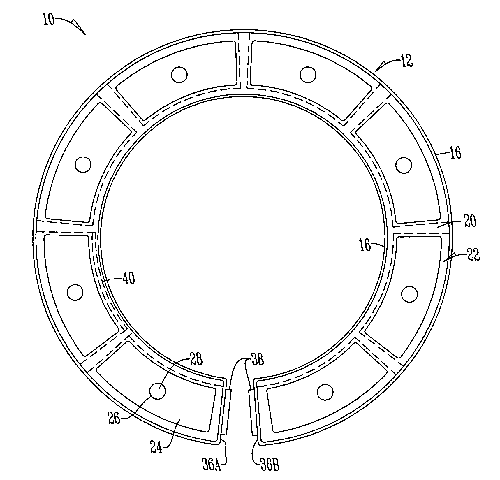
[0009]Referring to the figures, a neck support is shown by reference numeral 10. While a neck support is shown, by example only, the invention may be adapted for use with a helmet, chest protector, knee support, or the like.

[0010]The neck support 10 has a collar 12 having a bottom 14, sidewalls 16, and a removable top wall 18. Sectional walls 20 extend between the sidewalls 16 to form a compartment 22 that snugly receives a cell 24. The cell 24 is made of an elastomer and is of any shape or size. Each cell 24 has a port 26 with a check valve 28 disposed within the port 26.

[0011]The check valve 28 is of any type, structure and shape, but preferably has an outer body 30, an inner body 32, and a diaphragm 34 disposed therebetween that is capable of sealing an opening 35 in the inner and outer body. In addition, the check valve 28 preferably permits the release of air from the cell 24 when force is applied below a predetermined threshold level (i.e., under normal movement such as 5 p.s....


PUM


Abstract

A neck support/brace for protecting a neck has a flexible collar with a top wall, bottom wall, sidewalls and sectional walls disposed therebetween that form compartments therein. A plurality of cells are disposed within the compartment. Each of the fluid cells have a valve element disposed therein. When the pressure acting upon the cells is below a threshold pressure, fluid or air flows through the valve element to allow movement of the neck. Alternatively when the pressure on the cells is above the threshold pressure the valve element closes preventing fluid or air flow out of the fluid cell thus causing the cell to stay inflated and provide resistance to a neck movement.

Description


Claims


Application Information

Patent Timeline
Owner POWELL MARCUS W
Why Eureka
Try Eureka