
Method and apparatus for a wide field of view display

a wide field of view and display system technology, applied in the field of display systems, can solve the problems of poor suited display system to the use of wide aspect ratios typically used in high definition systems, current simulators that do not fully exploit the recent advances in visual display technology, and the loss of image resolution

Active Publication Date: 2009-08-13
THE BOEING CO
View PDF22 Cites 26 Cited by
  • Summary
  • Abstract
  • Description
  • Claims
  • Application Information

AI Technical Summary

Benefits of technology

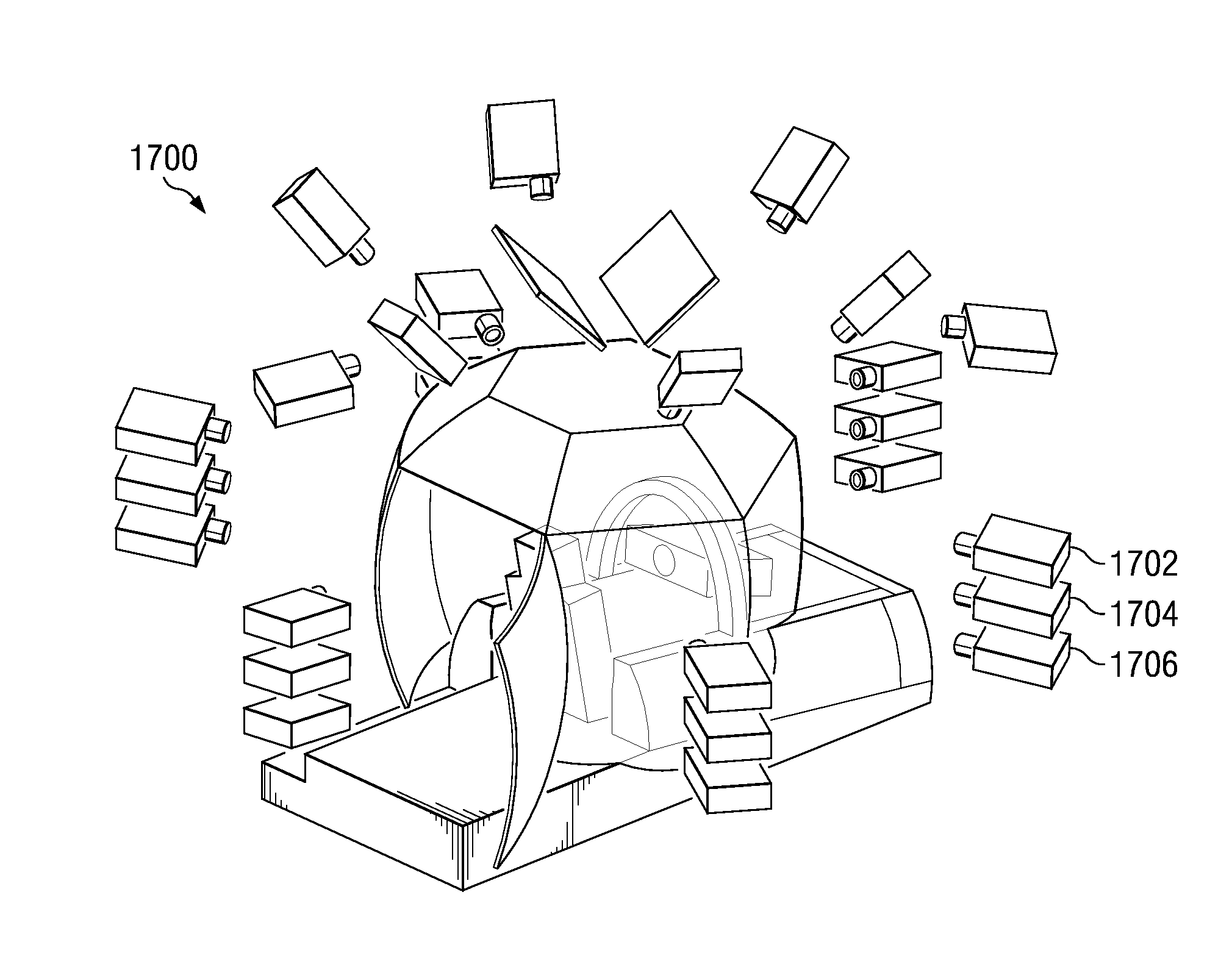
[0013]Thus, the advantageous embodiments provide a method and apparatus for creating a full field of view display system to overcome the problem of inefficient utilization of an image generator and display pixels when pixels are projected by fixed matrix high definition format projectors rather than analog CRT projectors to form a

Problems solved by technology

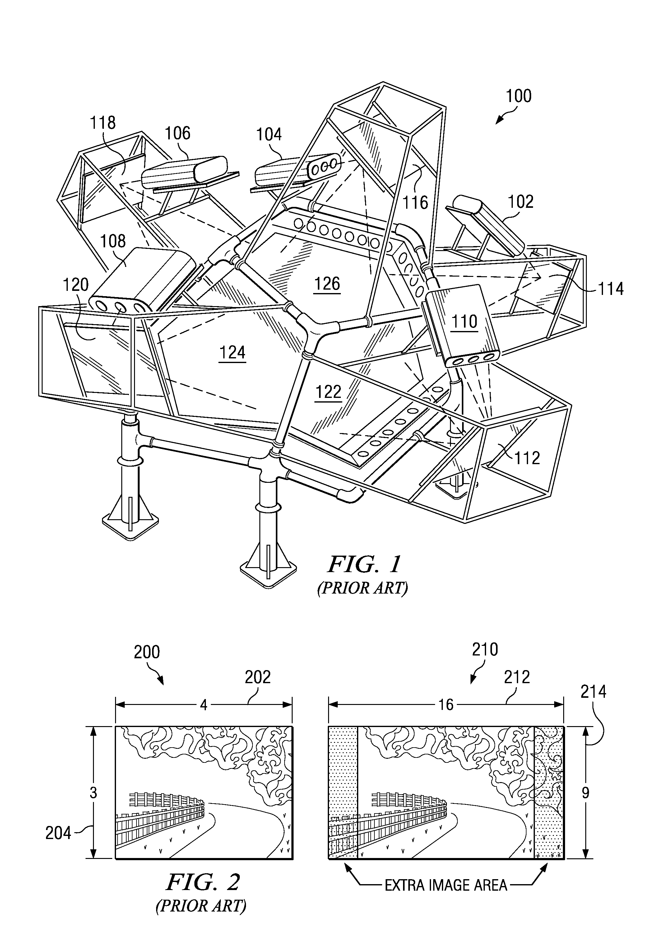
However, currently available simulators do not fully exploit the recent advances in visual display technology, such as fixed matrix digital projectors in general, and especially High Definition Television (HDTV) format fixed matrix projectors with wide aspect ratios, such as, without limitation, sixteen by nine (16:9) aspect ratio format.
Also, the modern fixed matrix projectors do not have the ability for image scaling without the loss of image resolution since the image source is made up of a mechanically fixed array of image sources instead of a continuous image surface, as with a CRT projector.
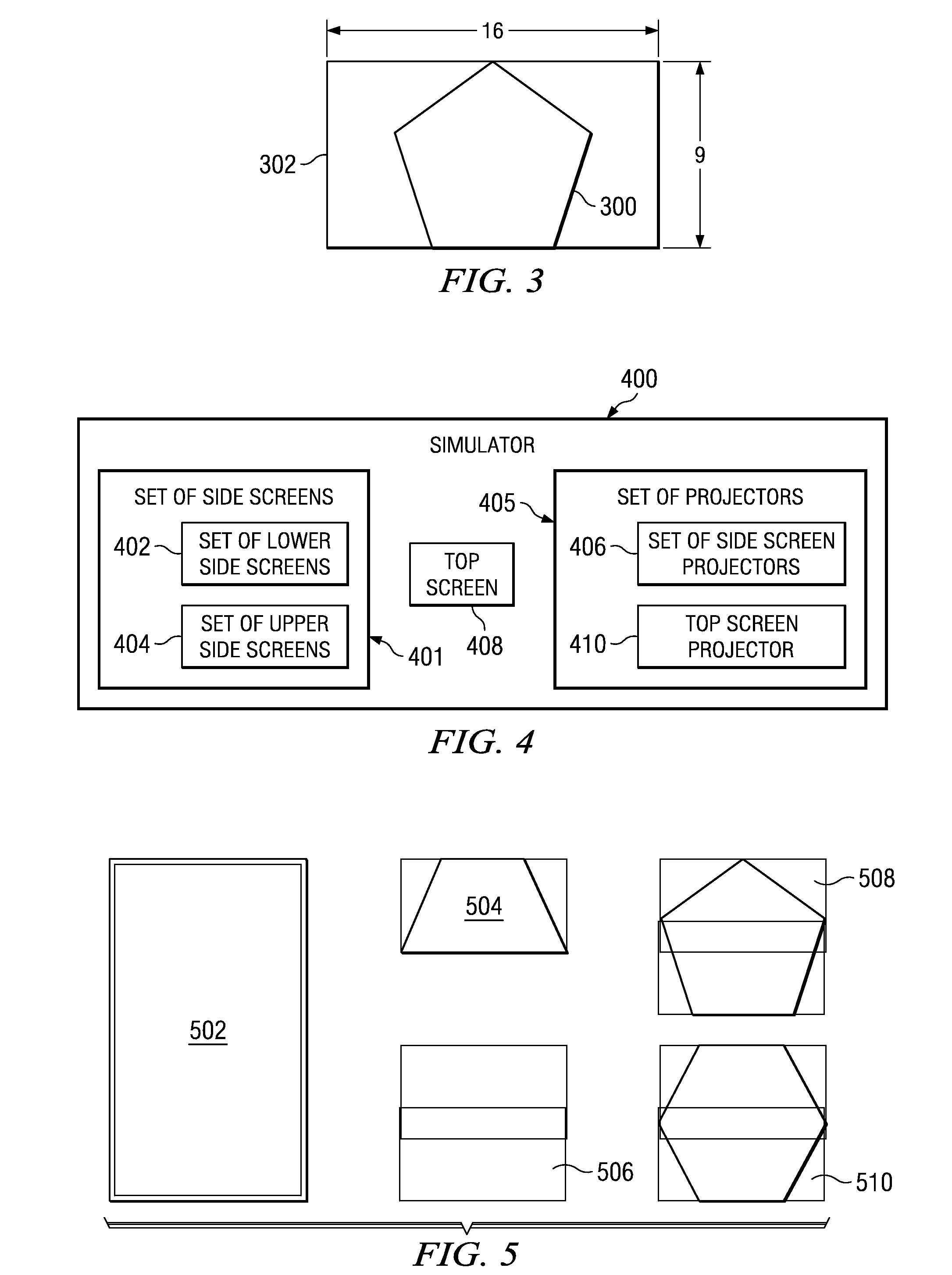
In addition, because the shape of the flat screen segments used to tessellate an arrangement of rear projection screens around the eyepoint in currently available simulators were designed for four by three (4:3) aspect ratio projectors, the resulting display systems are poorly suited to the use of wide aspect ratios typically used in high definition systems.
In other words, existing display system screens are not capable of providing an eye-limited full field of view display for simulators, such as aircrew training systems.

Method used


Image

  • Method and apparatus for a wide field of view display
  • Method and apparatus for a wide field of view display
  • Method and apparatus for a wide field of view display

Examples


Embodiment Construction

[0036]A simulator is a device that simulates a particular experience as realistically as possible. For example, a flight simulator simulates the experience of flying an aircraft, such as an airplane or helicopter. A vehicle driver simulator attempts to create the experience of driving a vehicle over streets or off-road terrains. Simulators typically use display systems to create a field of view displaying what the user might see if the user were actually flying an aircraft or driving a vehicle. The simulator may also provide simulated controls and steering devices associated with the particular aircraft or vehicle, and / or added motion to simulate movement of the aircraft or vehicle.

[0037]FIG. 1 is a block diagram of a prior art flight simulator. Flight simulator 100 is a cathode ray tube (CRT) type rear-projection system flight simulator. Flight simulator 100 includes cathode ray tube (CRT) projectors 102-110. Each of CRT projectors 102-110 produces a light beam carrying an image. T...


PUM


Abstract

A method and apparatus for a uniform resolution display screen. In one embodiment, the uniform resolution display screen comprises a surface of the uniform resolution display screen having a curvature configured to display images with a uniform resolution across the display screen. The curvature is based on a projection distance from a projector to the uniform resolution display screen and a viewing distance from an eyepoint of an observer to the uniform resolution display screen. The geometry of the display screen is configured to display images associated with a high definition imaging format.

Description

BACKGROUND INFORMATION[0001]1. Field[0002]The present disclosure relates generally to display systems. More particularly, the present application is directed to a method and apparatus for a visual image projection and display system that creates a wide field of view display using fixed matrix projectors that are preferably of high definition format.[0003]2. Background[0004]A simulator is a device that simulates a particular experience as realistically as possible. For example, a flight simulator simulates the experience of flying an aircraft, such as an airplane or helicopter. A vehicle driver simulator attempts to create the experience of driving a vehicle over streets or off-road terrains. Simulators typically use display systems to create a field of view displaying what the user might see if the user were actually flying an aircraft or driving a vehicle. Simulators may also provide simulated controls and steering devices associated with the particular aircraft or vehicle, and / or ...

Claims


Application Information

Patent Timeline
IPC IPC(8): H04N9/31
CPCG03B21/00G09B9/08H04N9/3197H04N9/3185H04N9/3188H04N9/3147G03B21/005
Inventor STREID, HAROLD R.VORST, CARL J.ROTHMAN, SCOTT PHILLIP
Owner THE BOEING CO
Learn More