Stepping motor

Inactive Publication Date: 2009-08-13
NIDEC SANKYO CORP
View PDF0 Cites 1 Cited by
  • Summary
  • Abstract
  • Description
  • Claims
  • Application Information

AI Technical Summary

Benefits of technology

[0015]In accordance with the present invention, even when the entire stepping motor is miniaturized, since aluminum or aluminum alloy whose specific gravity is smaller than that of stainless steel is utilized for the rotor shaft. Therefore, the weight of the rotor shaft is reduced and thus the inertial load of the rotor having the rotor shaft and the permanent magnet is reduced to improve a specified motor characteristic.
[0027]Further, according to the present invention, an output shaft where a lead screw part is formed is formed of aluminum or aluminum alloy, and it is structured that an outer diameter “D1” of the lead screw part and an outer diameter “D2” of a permanent magnet satisfy a certain relationship. Therefore, even when the diameter of the lead screw part is set to be smaller and the stepping motor is miniaturized, lowering of the maximum self-activation frequency can be prevented more effectively. As a result, a specified motor characteristic can be improved.

Problems solved by technology

Therefore, it is difficult to secure motor characteristics such as a starting performance and a response performance, for example, in the case of a CD / DVD player, it takes a lot of time to read data from a disk.
Further, when the size of a stepping motor is reduced, its generated torque is also decreased and thus an inertia of the lead screw part which has not been conventionally required to be considered too much significantly affects characteristics of the stepping motor, especially the maximum self-activation frequency.

Method used


Image

  • Stepping motor
  • Stepping motor
  • Stepping motor

Examples


Embodiment Construction

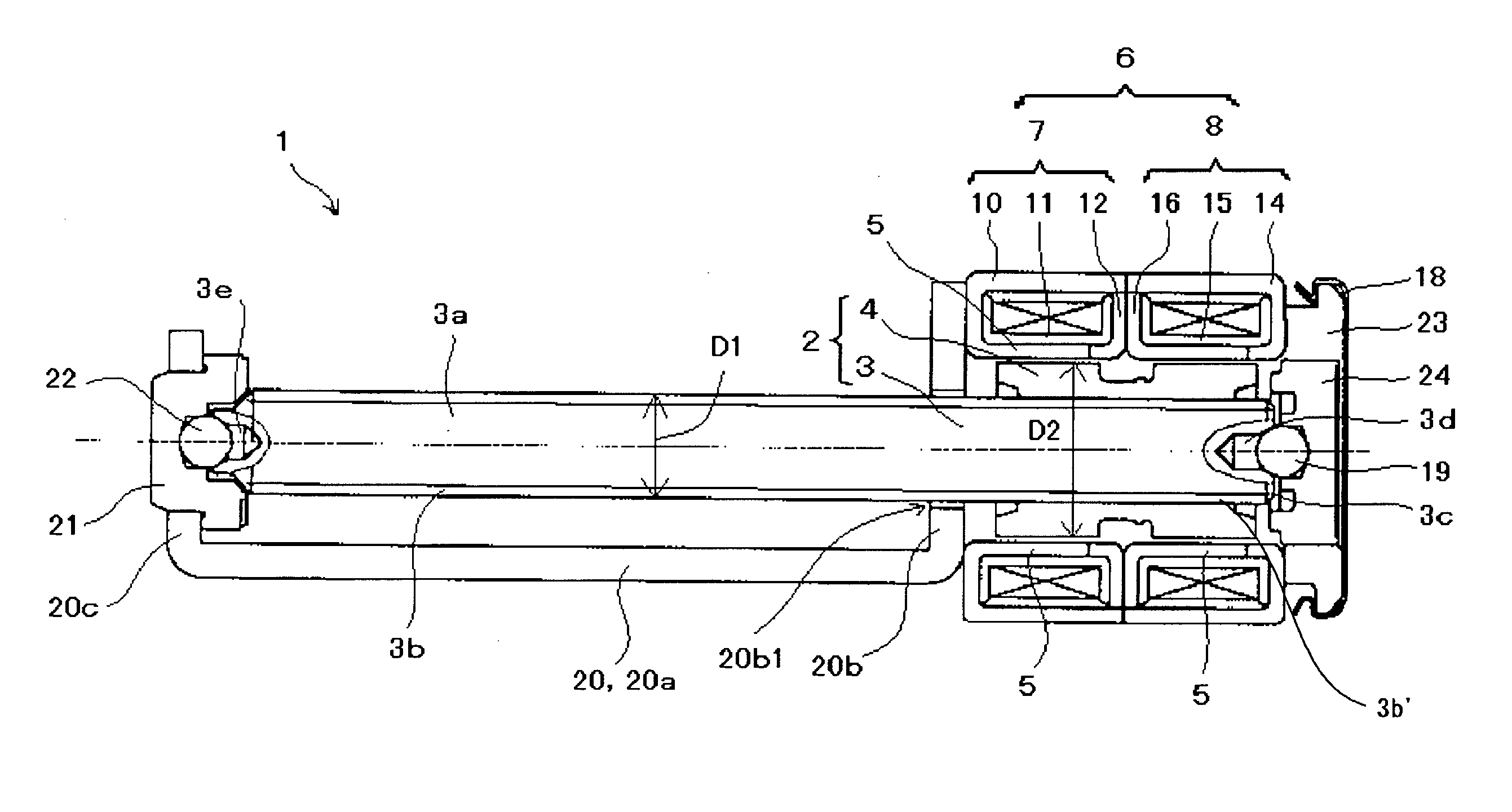
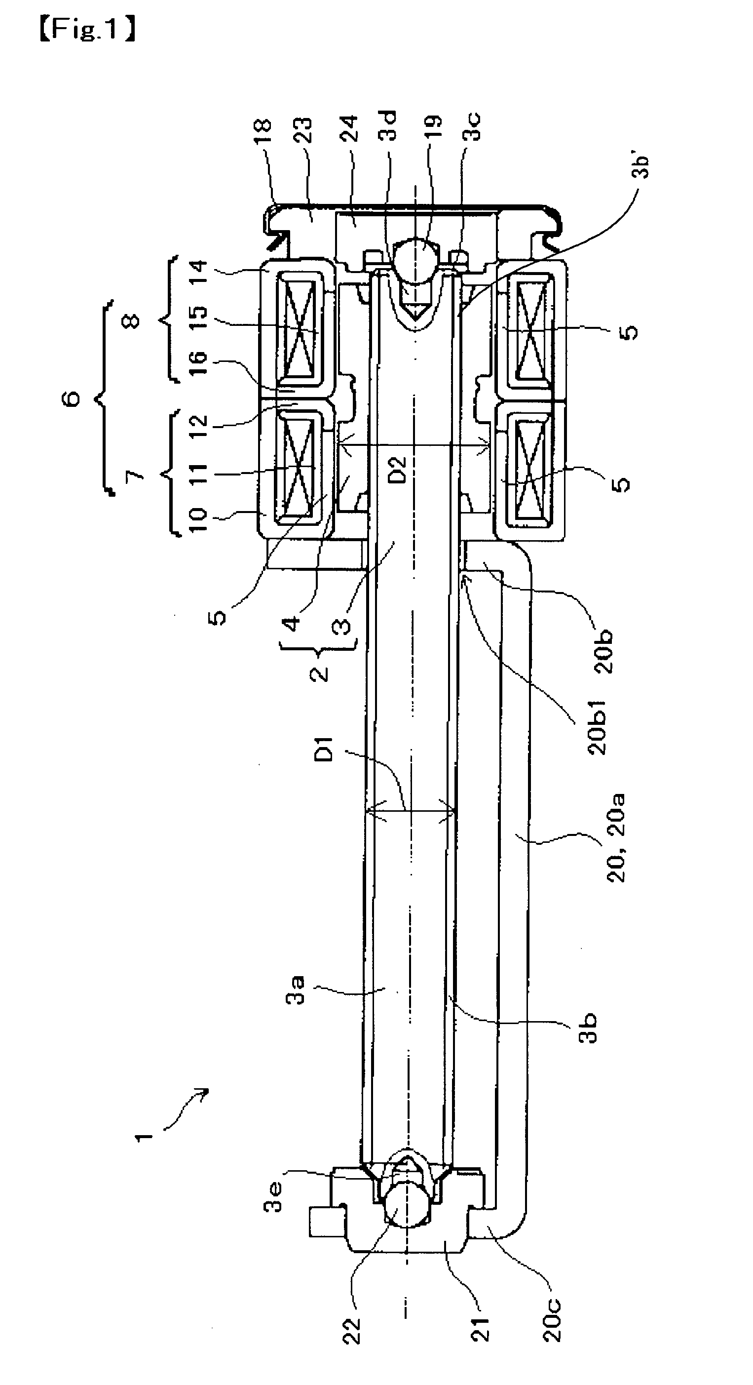
[0033]A stepping motor 1 in accordance with this embodiment is a so-called PM type of stepping motor, which includes a rotor 2 having a rotor shaft 3 and a cylindrical permanent magnet 4, a stator 6 having pole teeth 5 facing the permanent magnet 4 in a radial direction, and a frame 20 attached to a stator 6 on an output side of the rotor shaft 3. In addition, an output shaft 3a is integrally formed on the output side of the rotor shaft 3 so as to protrude from the stator 6. A lead screw part 3b is formed on the output shaft 3a. Further, a bearing hold member 23 is attached on an opposite output side of the stator 6 (base end 3c side of the rotor shaft 3) and a bearing 24 is held to the bearing hold member 23.

[0034]The rotor shaft 3 is formed of aluminum or aluminum alloy which is a nonmagnetic material, and a cylindrical permanent magnet 4 is fixed to its outer circumferential face by using an adhesive or the like. In this embodiment, an adhesive retaining portion 3b′ is formed at ...


PUM


Abstract

A stepping motor is provided with a rotor having with a rotor shaft A permanent magnet is attached to an outer peripheral side of the rotor shaft and a stator having pole teeth faces the permanent magnet in a radial direction. The stepping motor is characterized in that the rotor shaft is formed of aluminum or aluminum alloy.

Description

CROSS-REFERENCE TO RELATED APPLICATIONS[0001]This application claims priority to PCT Application PCT / JP2005 / 011426 filed Jun. 22, 2004, which is incorporated herein by reference.FIELD OF THE INVENTION[0002]The present invention relates to a small stepping motor and a lead screw part which is formed on an output side of its rotor shaft.BACKGROUND OF THE INVENTION[0003]As a motor for moving an object to be moved at a high speed such as an optical head device used in a CD / DVD player or the like or a lens group used in a video camera, a stepping motor has been known which is provided with a rotor, which includes a rotor shaft and a permanent magnet attached to an outer periphery of the rotor shaft, and a stator having pole teeth which face the permanent magnet in a radial direction. In this type of a stepping motor, for example, an output shaft protruding from the stator is provided on the output side of the rotor shaft and a lead screw part is formed on the output shaft. The lead screw...

Claims


Application Information

Patent Timeline
IPC IPC(8): H02K37/14H02K7/00H02K37/24
CPCH02K1/2786H02K37/24H02K7/003H02K1/28H02K1/2788
Inventor KOSHIDA, YOSHIAKIYAMAMOTO, TOSHIOMIYASHITA, TAKEYOSHI
Owner NIDEC SANKYO CORP
Why Eureka
Try Eureka