
Anesthesia device with stand-alone vaporizer apparatus

a stand-alone vaporizer and anesthesia device technology, which is applied in the direction of inhalators, medical devices, other medical devices, etc., can solve the problems of potentially less efficient operation of a control system comprising two disparate and remote user interfaces, and the need to control the anesthesia machine and the vaporizer through separate interfaces

Inactive Publication Date: 2009-08-06
GENERAL ELECTRIC CO
View PDF10 Cites 9 Cited by
  • Summary
  • Abstract
  • Description
  • Claims
  • Application Information

AI Technical Summary

Benefits of technology

[0004]The above-mentioned shortcomings, disadvantages and problems are addressed herein which will be understood by reading and understanding the following specification.

Problems solved by technology

One problem with some conventional anesthesia delivery systems is that the anesthesia machine and the vaporizer generally must be controlled via separate interfaces.
It can be seen that it is potentially less efficient to operate a control system comprising two disparate and remotely located user interfaces as compared to a control system implementing a single interface.

Method used


Image

  • Anesthesia device with stand-alone vaporizer apparatus
  • Anesthesia device with stand-alone vaporizer apparatus

Examples


Embodiment Construction

[0010]In the following detailed description, reference is made to the accompanying drawings that form a part hereof, and in which is shown by way of illustration specific embodiments that may be practiced. These embodiments are described in sufficient detail to enable those skilled in the art to practice the embodiments, and it is to be understood that other embodiments may be utilized and that logical, mechanical, electrical and other changes may be made without departing from the scope of the embodiments. The following detailed description is, therefore, not to be taken as limiting the scope of the invention.

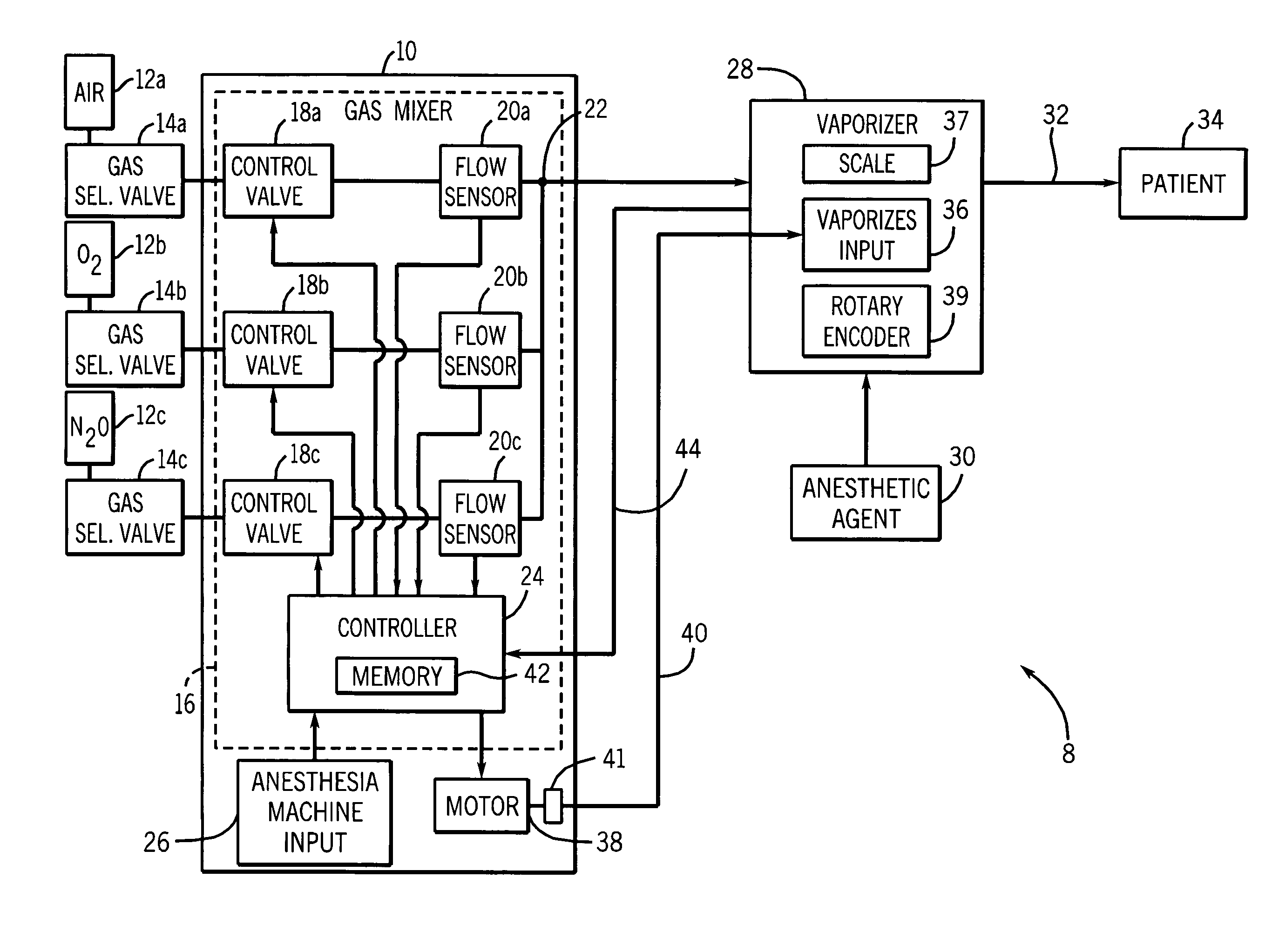
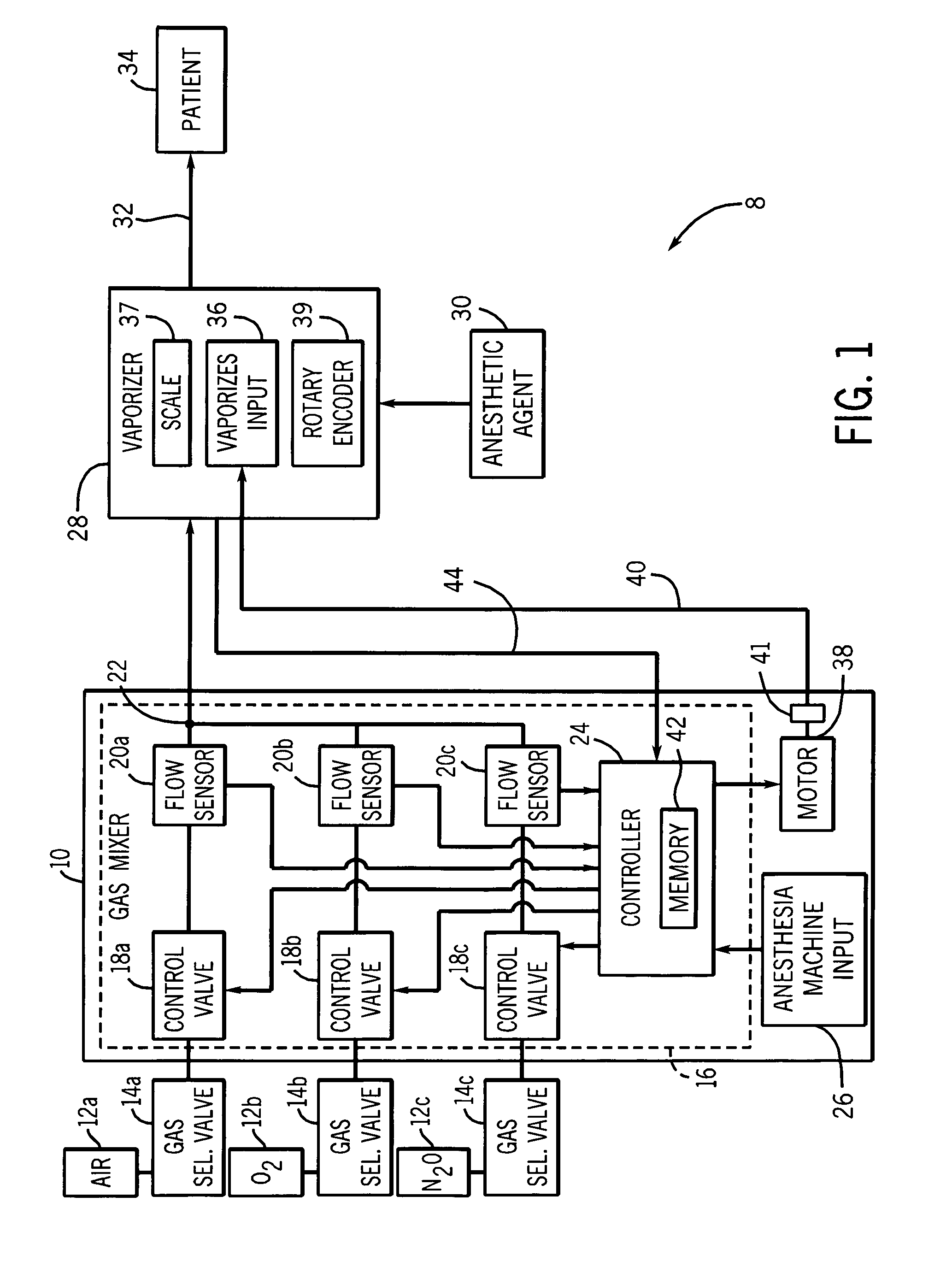
[0011]Referring to FIG. 1, an anesthesia system 8 is schematically depicted in accordance with one embodiment. The anesthesia system 8 includes an anesthesia machine 10, a plurality of gas storage devices 12a, 12b and 12c, and a stand-alone vaporizer 28. The anesthesia machine 10 is shown for illustrative purposes and it should be appreciated that other types of anesthesia mac...


PUM


Abstract

An anesthesia system is disclosed herein. The system includes an anesthesia machine comprising an anesthesia machine input, and a stand-alone vaporizer connected to the anesthesia machine. The stand-alone vaporizer includes a vaporizer input. The stand-alone vaporizer is configured to produce a selectable concentration of an anesthetic agent. The anesthesia machine input and the vaporizer input may be independently implemented to regulate the concentration of the anesthetic agent from the stand-alone vaporizer.

Description

BACKGROUND OF THE INVENTION[0001]The subject matter disclosed herein relates to a system comprising an anesthesia device and a stand-alone vaporizer.[0002]Conventional anesthesia delivery systems include an anesthesia machine pneumatically coupled with a remotely located stand-alone vaporizer. The anesthesia machine generally receives a plurality of different gasses such as air, O2 and / or N20 from a wall outlet and combines them in a selectable manner. The stand-alone vaporizer introduces a selectable concentration of vaporized anesthetic agent into the gas mixture. The vaporized anesthetic agent and gas mixture are then transferred to a patient.[0003]One problem with some conventional anesthesia delivery systems is that the anesthesia machine and the vaporizer generally must be controlled via separate interfaces. As an example, an operator must generally set the individual concentrations of the air, O2 and N20 using a first interface disposed on the anesthesia machine, and must the...

Claims


Application Information

Patent Timeline
IPC IPC(8): A61M16/01
CPCA61M16/0051A61M16/01A61M16/104A61M16/18A61M2205/52A61M2202/0208A61M2202/0283A61M2205/502A61M2016/0039A61M16/024
Inventor THOM, MARK ALANTHAM, ROBERTPINKERT, JOHN RAYMONDJUNGWIRTH, ANDREW
Owner GENERAL ELECTRIC CO
Learn More