Door hinge with a hidden closure system

Inactive Publication Date: 2009-08-06
IRWIN ROBERT
View PDF36 Cites 8 Cited by
  • Summary
  • Abstract
  • Description
  • Claims
  • Application Information

AI Technical Summary

Benefits of technology

[0010]Accordingly, a feature and advantage of the present invention is its ability to provide a door hinge with a non-continuously latched closure system, thus allowing the door to swing freely when the mechanism is released.
[0011]Another feature and advantage of the present invention is its ability to provide a door hinge wherein the closure system is hidden within the door jam, door frame or within the door, rendering an enhanced aesthetic appearance.
[0012]Still another feature and advantage of the present invention is its ability to provide a closure cylinder utilizing hydraulic oil, nitric oxide, air or other compressible material.
[0013]Yet another feature and advantage of the present invention is its ability to provide a door hinge that softly closes the door reducing the sound of closure during the final approach of the door.
[0014]Yet another feature and advantage of the present invention is its ability to provide a door hinge with a soft closure system that prevents a door from rapid opening or closing so as to protect the door, doorframe, or surroundings from being damaged.
[0015]Yet another feature and advantage of the present invention is its ability to provide a door hinge with a soft closure system that cushions door closure, thereby reducing the stress on the door, hinge, latch / lock and frame.

Problems solved by technology

Moreover, such door closing systems apply a non-uniform force to the upper portion of the door disadvantageously resulting in a force offset from the rotational axis of the hinge assembly, thus deforming the door, hinge, latch / lock and frame over time.
Furthermore, spring-based door closing systems frequently lose their resilient effect after lengthy period of service and will thereafter cause incomplete closing of the door.
When a door is closed with the assistance of such door closing systems, it is typically forced to move in its closing direction rapidly, causing a noise to the ear and forceful impact, wherein the main elements of such a hinge, lock and door elements are impaired over time due to such force.
Furthermore, both hydraulic and spring door closing systems generally limit the radial travel of the door, to for example 90 degrees variation between close and open.

Method used


Image

  • Door hinge with a hidden closure system
  • Door hinge with a hidden closure system
  • Door hinge with a hidden closure system

Examples


Embodiment Construction

[0037]In describing the preferred and alternate embodiments of the present invention, as illustrated in FIGS. 1-7, 10 and 11 specific terminology is employed for the sake of clarity. The present invention, however, is not intended to be limited to the specific terminology so selected, and it is to be understood that each specific element includes all technical equivalents that operate in a similar manner to accomplish similar functions.

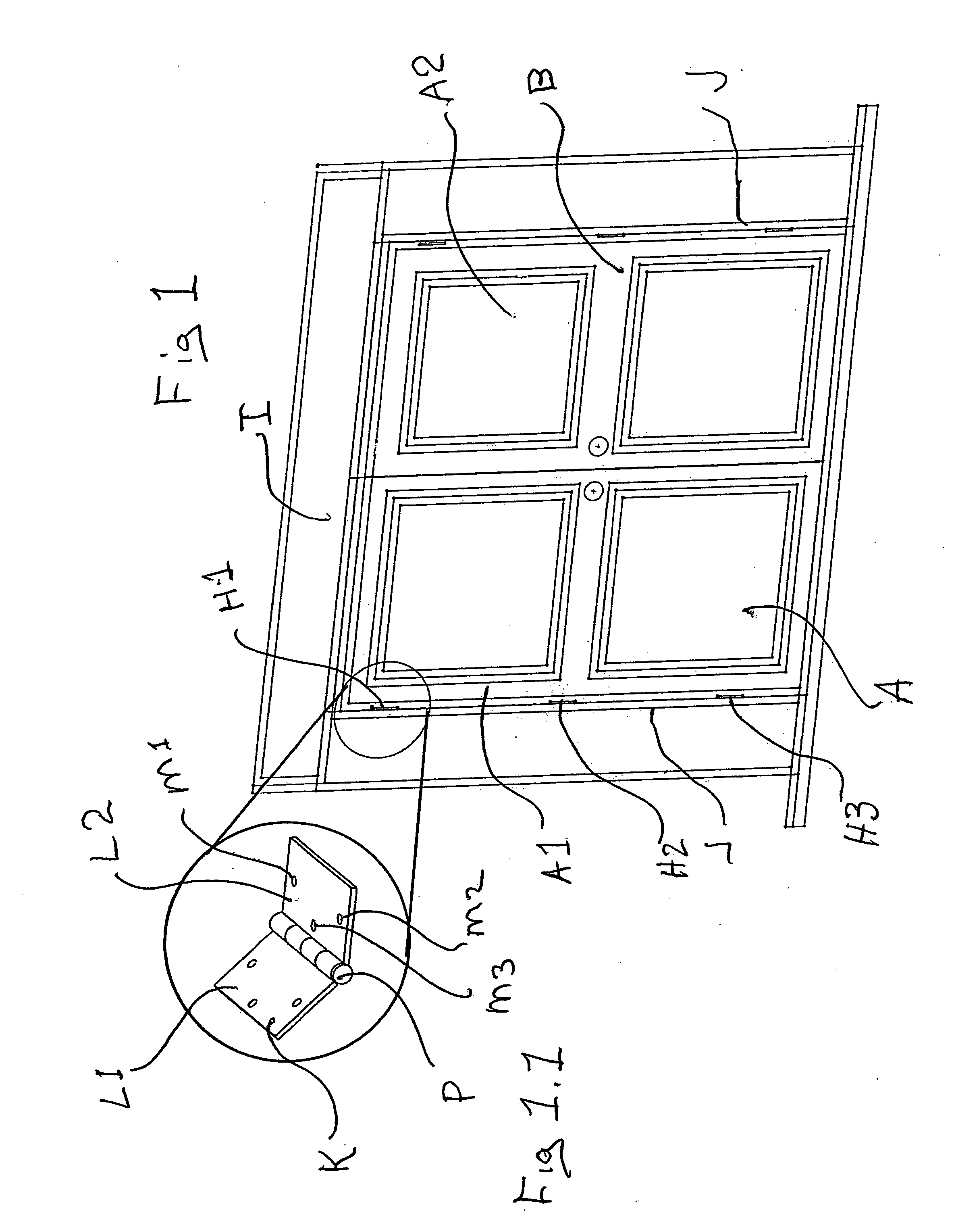
[0038]Referring now to FIGS. 1 and 1.1, there is depicted a prior art door A and door B shown in a side-by-side configuration, door jam J, door header I and a three hinge assembly H1, H2, and H3. The door A, which may swing inward, toward the viewer as depicted in FIG. 1, fits closely to the jam J at both its hinge edge A1 and its opposite or latch edge A2. Door B is positioned in a similar manner. Such door A and door B may be configured to swing inward or outward by switching the configuration of hinge assembly H1, H2, and H3. It should be noted, al...


PUM


Abstract

A door hinge with a hidden closure system comprising, in general, a first hinge with a pin protruding from the face of the hinge, a second hinge with a hidden closure system, wherein such pin engages a latch and release mechanism and triggers a closure system in the second hinge during final approach, thus softly closing the door and reducing the sound of closure during the final approach of the door.

Description

RELATED APPLICATIONS[0001]The present Nonprovisional Application is related to, and hereby claims priority to and the benefit of, U.S. Provisional Application No. 60 / 898,162, entitled “Door Hinge with a Hidden Closure System,” filed on Feb. 2, 2007.FIELD OF THE INVENTION[0002]The present invention relates generally to door hinge and more specifically to a door hinge with a hidden closure system for soft closure of the door.BACKGROUND OF THE INVENTION[0003]The conventional door hinge is composed of two leaves each engaging with the other by means of a pivot pin and sleeve. One leaf is fixed on the door edge and the other is fixed on the door frame. One or more hinges are used to pivot the door when opening or closing the door. For automatically closing the door with a conventional hinge, a hydraulic system, spring system or a combination system is typically affixed to the upper portion of door and to the horizontal beam of the upper door frame, thereby adding an industrial appearance...

Claims


Application Information

Patent Timeline
IPC IPC(8): E05D11/02E05D5/10
CPCE05F3/20E05F5/027Y10T16/5373E05Y2900/132Y10T16/557E05Y2201/478E05D5/04
Inventor IRWIN, ROBERT
Owner IRWIN ROBERT
Why Eureka
Try Eureka