Method and apparatus for detecting defects on a disk surface

a technology of a disk surface and a detection method, applied in the direction of material analysis, instruments, transmission, etc., can solve the problems of affecting the accuracy of magnetic reading and writing operations, unstable floating amount of a head, and deterioration of the characteristics of a product, so as to accurately distinguish and detect defects

Inactive Publication Date: 2009-07-30
HITACHI HIGH-TECH CORP
View PDF2 Cites 10 Cited by
  • Summary
  • Abstract
  • Description
  • Claims
  • Application Information

AI Technical Summary

Benefits of technology

[0011]The present invention provides an apparatus for detecting defects on a disk surface that can accurately distinguish and detect defects without overlooking the wrinkle defects.
[0016]According to the present invention, the wrinkle defect, which is a low aspect defect, can be detected while suppressing false reports but not overlook the defects regardless of the generation direction of the wrinkle defect. Therefore, the present invention is advantage in that the quality of the detected disk is secured and in some cases, the yield of the disk product can be increased, and the production efficiency of the disk can be increased.

Problems solved by technology

When there are defects on the surfaces of these materials, characteristics of a product are deteriorated.
If the above defect exists on the disk surface, it makes a floating amount of a head unstable and affects the accuracy of magnetic reading and writing operations.
As a result, this defect is considered as a serious defect.
However, since the increase and decrease of the signal are extremely small in the wrinkle defect portion, it is difficult to detect the wrinkle defect having extremely low aspect ratio among the low aspect defects.
When detecting the wrinkle defects using an apparatus for detecting defects on a disk surface according to the related art, there are two problems as follows.
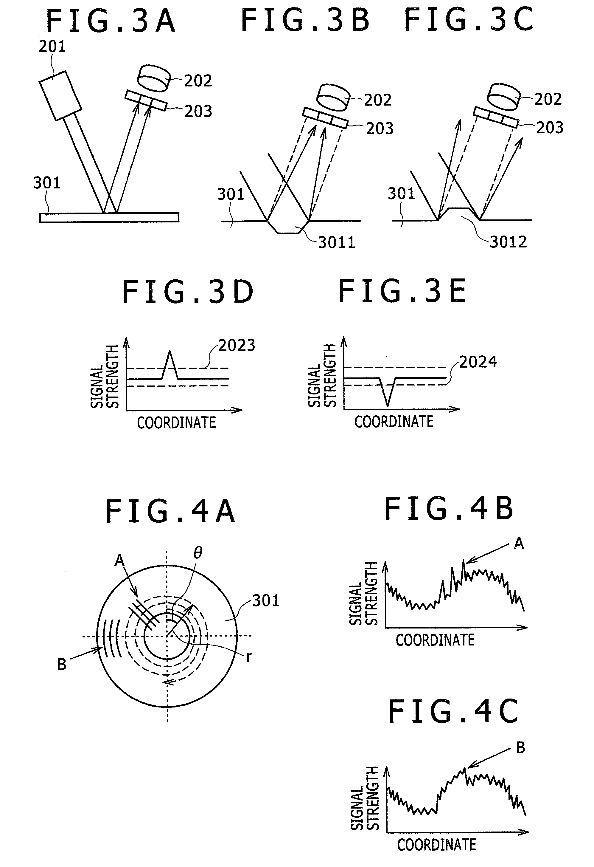
The first problem is that the apparatus for detecting defects on a disk surface according to the related art detects the disk in a spiral shape as shown in FIG. 4 and performs a threshold process using a one-dimensional signal as a signal process.
However, if the signal strength is extremely small, when the threshold process is performed on the signal, the signal change can be hidden in the defect portion A by the change in the signal strength due to the waviness of the disk.
In this case, it is difficult to detect the defects even by using the filter process.
The second problem is that even if there is the signal strength signal in the wrinkle defect portion like the defect portion A, since the change in the signal strength is extremely small, the defects may be overlooked due to the setting of the threshold or a large amount of false reports may be generated.
Further, distinguishing between the kinds of defects having linear or circular arc features, even if they are detected, are insufficient.
There is a problem of having a bad effect on a hard disk or a problem of generating a large amount of false reports by overlooking the wrinkle defect such that it is very inconvenient as the apparatus for detecting defects on a disk surface.

Method used


Image

  • Method and apparatus for detecting defects on a disk surface
  • Method and apparatus for detecting defects on a disk surface
  • Method and apparatus for detecting defects on a disk surface

Examples


first embodiment

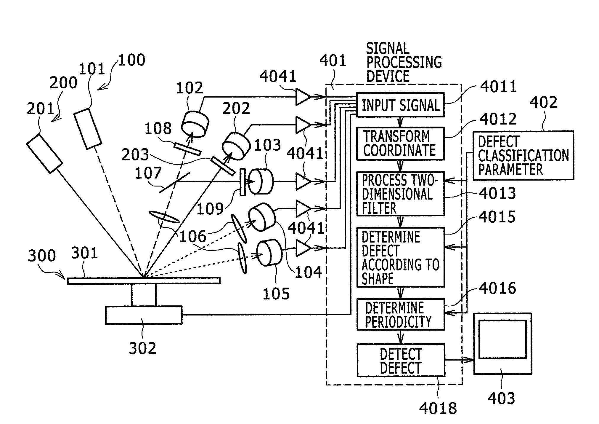
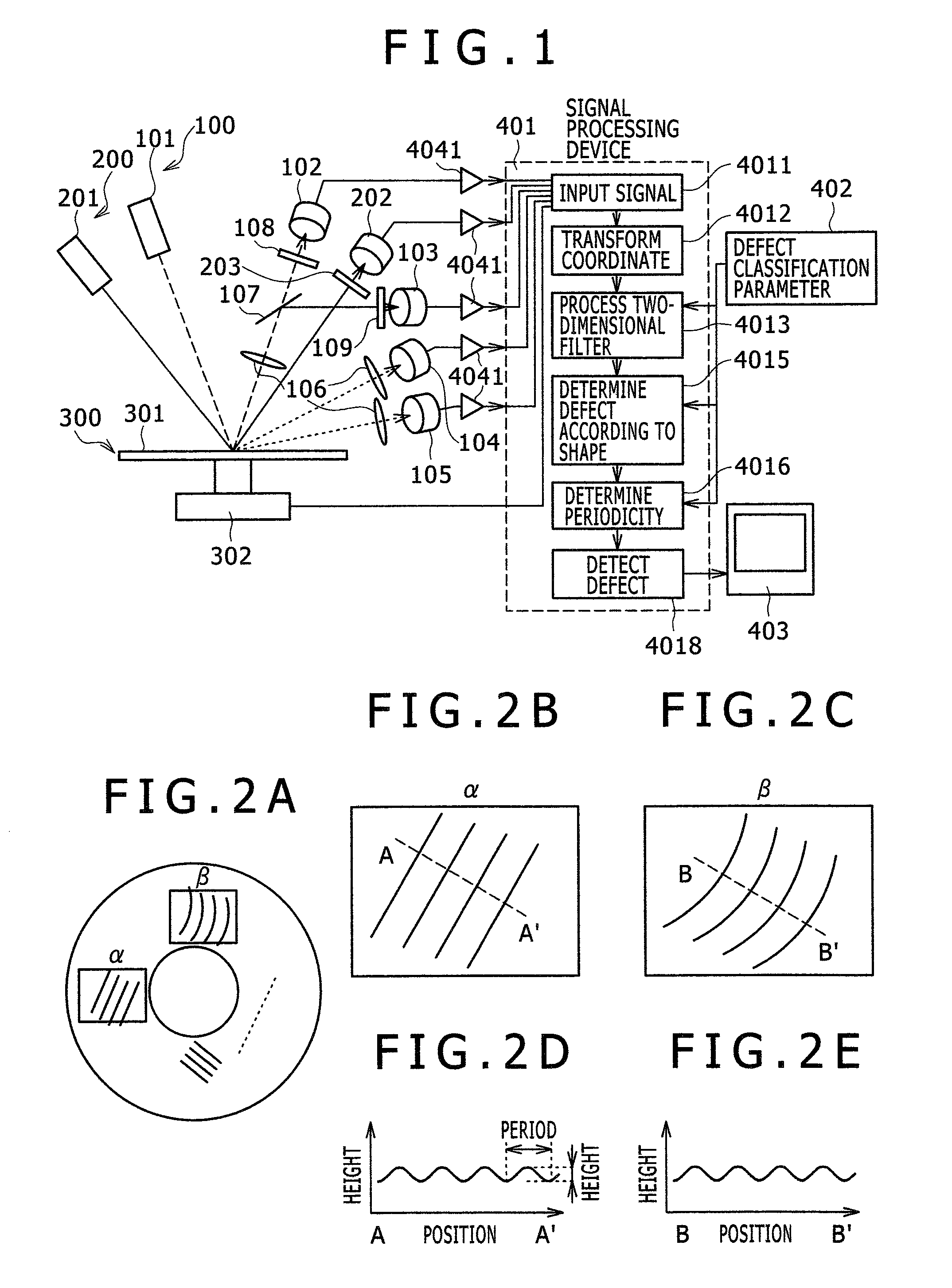
[0068]FIG. 1 is a diagram schematically showing an entire configuration of an apparatus for detecting defects on a disk surface according to a first embodiment. As shown in FIG. 1, the apparatus for detecting defects on a disk surface includes dual optical systems 100 and 200 that are each configured with a light transmitting system and a light receiving system. For example, the first optical system 100 detects pit, handling damage, stain, particle, and scratch defects and the second optical system 200 detects bump, dimple, and glide defects. In other words, the plural optical systems are disposed according to the kind of defect. The first light transmitting system 101 projects light to form laser spots on a surface of a disk 301, and the second light transmitting system 201 projects parallel light having a predetermined width, which can detect defects, on the surface of the disk 301 and at the same time, scans the position thereof on the surface of the disk 301 in a spiral shape at...

second embodiment

[0091]Next, the determination method of the wrinkle defect generated in the circular arc shape will be described as the second embodiment. FIG. 14 describes an image processing flow on the defect having the features of the circular arc distribution. The processing contents from 4011 to 4013 of FIG. 14 are the same as the process described in FIG. 7.

[0092]Next, the extraction of circular arc component of the image binarized by the process is performed (40141). As an example for performing the circular arc detection, the Hough transform method is used. FIGS. 15A and 15B show a principle of the Hough transformation. For example, in FIG. 15A, if three points, that is, P1, P2, and P3 exist on the same circle having a radius r, the circle equation becomes the following equation.

(x−a)2+(y−b)2=r2   [Equation 8]

[0093]However, a and b become the center coordinate of a circle. The method for obtaining the center coordinate (a and b) indicates the circle having the radius r based on the points ...

third embodiment

[0104]Although the first embodiment relates to the detection of the periodicity linear defect and the second embodiment relates to the detection of the periodicity circular arc defect, it is preferable to simultaneously perform detection of these defects in the same apparatus. In this case, in the flow chart of FIG. 7, it is preferable that after the straight line detection step (4014) and the linear defect determination step (4015) or simultaneously with the above steps, the circular arc detection step (40141) and the circular arc defect determination step (40161) shown in FIG. 14 are performed. Thereby, it is possible to detect the periodicity linear defect and the periodicity circular arc defect, which are the wrinkle defect of the disk.


PUM

PropertyMeasurementUnit
frequencyaaaaaaaaaa
lengthaaaaaaaaaa
heightaaaaaaaaaa

Abstract

The present invention relates to an apparatus for detecting defects on a disk surface which projects light on the disk surface by a light transmitting system, receives specula reflection light and scattered light by a light receiving system, exposes defects by performing a two-dimensional frequency filter process on a signal, and performs a defect determination process to extract a linear-shaped isolative defect candidate. Next, the present invention performs a periodicity determination process to classify and detect the periodically generated linear and circular arc defects and the isolatively generated linear and circular arc defects.

Description

BACKGROUND OF THE INVENTION[0001]1. Field of the Invention[0002]The present invention relates to detect defects on a disk surface, and more particularly, to a method and apparatus for detecting linear defects and circular arc defects that exist on a disk surface and periodically occur.[0003]2. Description of the Related Art[0004]As a material of an information recording medium or a semiconductor, a disk such as glass, silicon wafer, and the like is used. When there are defects on the surfaces of these materials, characteristics of a product are deteriorated. As a result, detection of these defects is performed by an apparatus for detecting defects on a disk surface. The apparatus for detecting defects on the disk surface detects the defects generated on the disk surface. There are various kinds of defects, for example, fine dust (particle) attached to the surface, spot (stain), abrasion mark (scratch) due to foreign materials, fine concave portions (pit) or convex portions (bump), s...

Claims


Application Information

Patent Timeline
Patent Type & Authority Applications(United States)
IPC IPC(8): G01N21/88G06F15/00
CPCG01N21/8922G01N21/9501G01N2021/8854G01N2021/8825G01N21/9506
Inventor HARIYAMA, TATSUOSASAZAWA, HIDEAKIYOSHIDA, MINORUSERIKAWA, SHIGERU
Owner HITACHI HIGH-TECH CORP
Why Eureka
Try Eureka