
Topology maintenance and discovery facility for downhole networks

Active Publication Date: 2009-07-30
INTELLISERV
View PDF13 Cites 28 Cited by
  • Summary
  • Abstract
  • Description
  • Claims
  • Application Information

AI Technical Summary

Benefits of technology

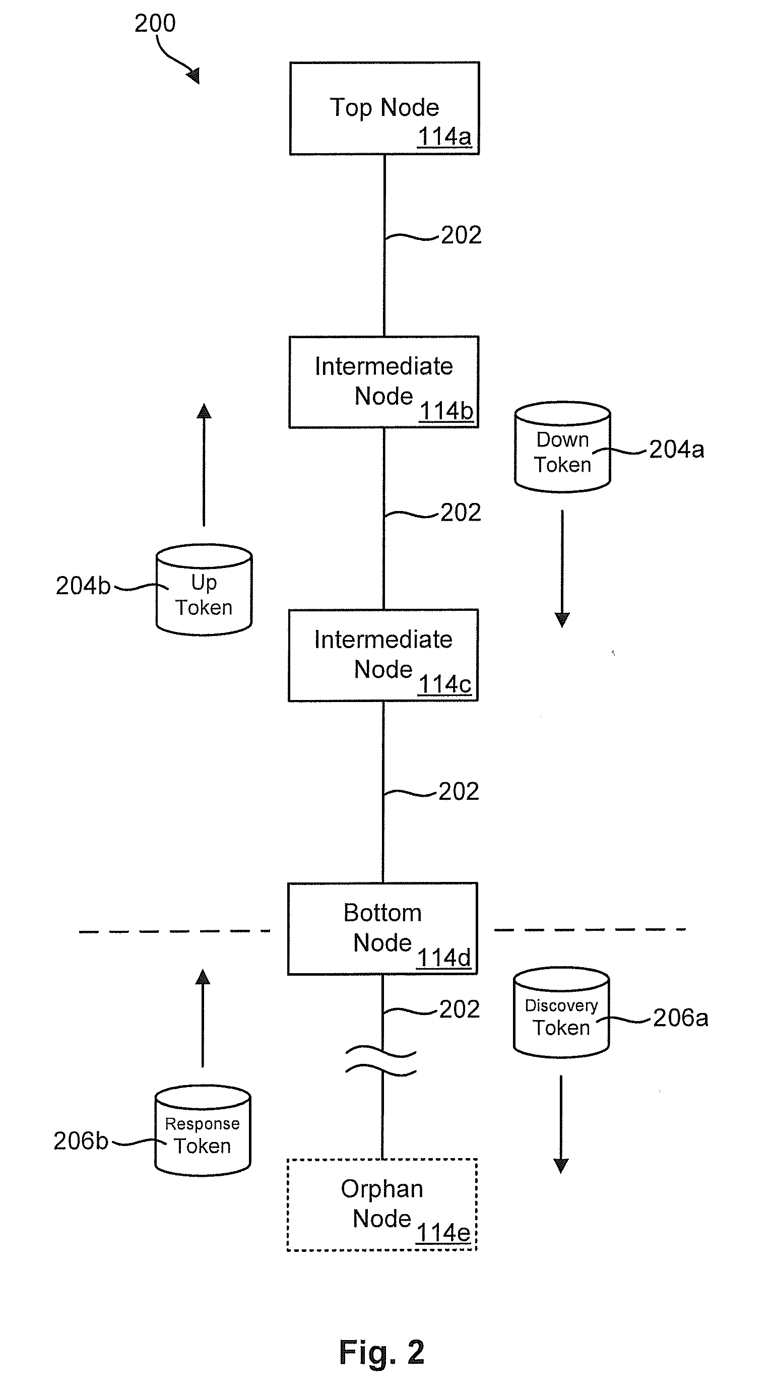
[0009]In a first aspect of the invention, a method for discovering and monitoring multiple nodes in a downhole network may include receiving data packets originating from several downhole nodes. These packets may be read to extract a unique identifier and hop count for each of the nodes. This information may then be used to create entries in a network topology table corresponding to each of the downhole nodes. Each entry may contain a unique identifier identifying a node and a hop count identifying a location of the node within the downhole network. The method may further include modifying one or more entries in the topology table that have a hop count that conflicts with the hop count of a more recently created or updated entry. This helps ensure that the hop counts of each entry are unique.
[0012]In another aspect of the invention, a computer-readable medium is disclosed to store a program of computer-executable instructions configured to perform operations to discover and monitor a collection of nodes in a downhole network. In selected embodiments, these operations may include receiving data packets originating from multiple downhole nodes and reading the packets to extract a unique identifier and hop count for each node. An entry for each node may be created in a network topology table to store the unique identifier and hop count. Operations may be included to modify one or more of the entries in the topology table that have hop counts that conflict with the hop count of a more recently created or updated entry. This helps ensure that the hop counts of each entry are unique.

Problems solved by technology

Very few approaches, however, have achieved commercial implementation due to the high costs of development and constraints imposed by the downhole environment.
Nevertheless, implementing and maintaining a network in a downhole environment is a difficult task.
In other cases, breaks may occur in transmission lines or other transmission components that may cause particular nodes or groups of nodes to temporarily or permanently lose communication with the surface.
These characteristics make it a challenge to discover, monitor, and manage network components in a downhole environment.

Method used


Image

  • Topology maintenance and discovery facility for downhole networks
  • Topology maintenance and discovery facility for downhole networks
  • Topology maintenance and discovery facility for downhole networks

Examples


Embodiment Construction

[0029]It will be readily understood that the components of the present invention, as generally described and illustrated in the Figures herein, could be arranged and designed in a wide variety of different configurations. Thus, the following more detailed description of the embodiments of apparatus and methods in accordance with the present invention, as represented in the Figures, is not intended to limit the scope of the invention, as claimed, but is merely representative of certain examples of presently contemplated embodiments in accordance with the invention. The presently described embodiments will be best understood by reference to the drawings, wherein like parts are designated by like numerals throughout.

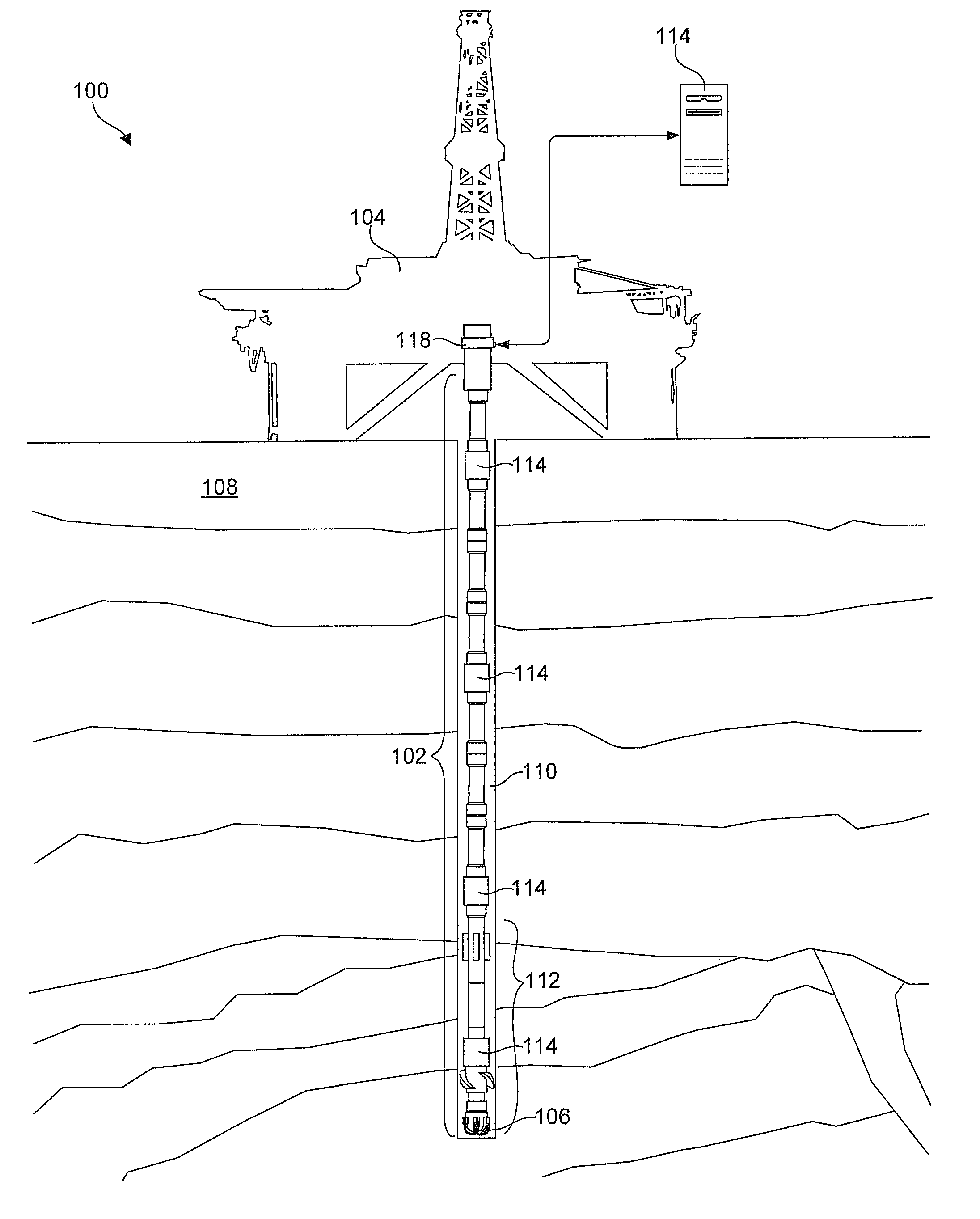
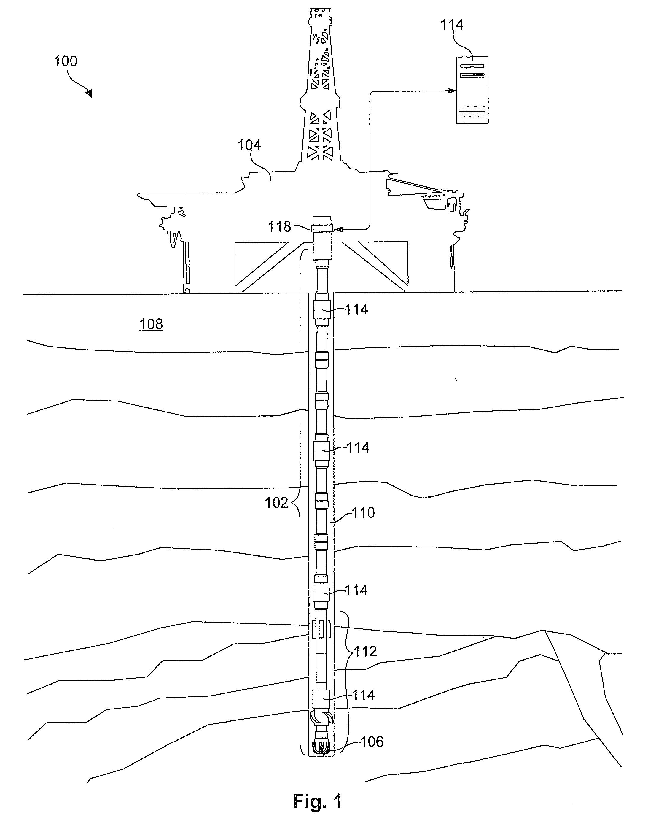
[0030]Referring to FIG. 1, one embodiment of a downhole drilling system 100 for use with the present invention may include a drill string 102 comprising multiple sections of drill pipe and other downhole tools. The drill string 102 may be rotated by a drill rig 104 to turn ...


PUM


Abstract

An apparatus and method for discovering and monitoring a collection of nodes in a downhole network may include receiving data packets originating from several downhole nodes. These packets may be read to extract a unique identifier and hop count for each of the nodes. This information may then be used to create entries in a network topology table corresponding to each of the downhole nodes. Each entry may contain unique identifier identifying the respective node and a hop count identifying a location of the node within the downhole network. The apparatus and method may further include modifying one or more entries in the topology table having conflicting hop counts to ensure that the hop counts of each entry are unique.

Description

BACKGROUND OF THE INVENTION[0001]1. Field of the Invention[0002]This invention relates to downhole drilling and more particularly to apparatus and methods for managing and discovering network topology in a downhole drilling environment.[0003]2. Description of the Related Art[0004]The ability to transmit data at high speeds along a drill string is a current goal and project of the downhole drilling industry. More and better information at the surface has the ability to significantly decrease drilling costs by enabling operators to more accurately direct the drill string to hydrocarbon deposits. Such information may also improve safety and reduce the environmental impacts of drilling. This technology may also be desirable to take advantage of numerous advances in the design of tools and techniques for oil and gas exploration, and may be used to provide real-time access to data such as temperature, pressure, inclination, salinity, and the like, while drilling.[0005]In order to transmit...

Claims


Application Information

Patent Timeline
IPC IPC(8): G01V3/00
CPCG01V11/002E21B47/12
Inventor JOHNSON, MONTESTILLINGS, MARK
Owner INTELLISERV
Learn More