
Vacuum friction feeder

a friction feeder and vacuum technology, applied in the direction of thin material processing, article separation, transportation and packaging, etc., can solve the problems of difficult, if not impossible, to feed different types of flat stock, use the same friction feeder, and conventional devices have a difficult time feeding long, dense, wide flat stock

Active Publication Date: 2009-07-30
WALLACE ROBERT BRIAN
View PDF14 Cites 3 Cited by
  • Summary
  • Abstract
  • Description
  • Claims
  • Application Information

AI Technical Summary

Benefits of technology

"The present invention is a vacuum friction feeder that overcomes the limitations of conventional vacuum friction feeders. It is a bottom-feed vacuum friction feeder that is suitable for use in mail handling, printing, and packaging industry. The feeder includes a vacuum friction belt with holes, rollers, a suction port, and an exposure table. The exposure table has a horizontal surface that supports a stack of products, and the belt rotates around the table to create suction pressure through the holes. The exposed portion of the product is adjusted by moving the exposure table relative to the table top. The feeder can handle a wide variety of products, including heavy and thin ones, and can also feed long and wide products."

Problems solved by technology

One of the problems that exists with conventional friction feeders is that it is often difficult, if not impossible, to feed different types of flat stock (e.g., flat stock which is thick, or rigid, or wide, or limp etc.) using the same friction feeder.
Conventional devices have a difficult time feeding long, wide, dense flat stock (e.g., 36″×16″ paper feed bags).
In such applications, it is difficult to make appropriate adjustments to the “wedge” to expose an optimal amount of the material to the belts.
Therefore, it is difficult to obtain enough control over the amount of exposure, particularly with longer products, to consistently feed product one at a time (i.e., without feeding multiple pieces at a time).
Another problem with feeding dense (heavy) material is the amount of material that may be loaded into the stack or “hopper”.
The angled design of conventional devices limits the amount of material that can be loaded into the hopper.
So as the material is feed and the hopper is depleted the feed characteristic is changed causing feed issues.
All these problems make it difficult for the operator to setup and run current device in an effective manner.
Loading various size products is problematic because of the wedge design.
With the conventional wedge design, the height at which the operator has to load the hopper becomes a major issue.
Feeding limp feed stock is also a problem for conventional friction feeders.
In such applications, the product exposure wedge has to be set so close to the leading edge that the back of product becomes basically unsupported, which causes problems feeding when any significant amount of product is loaded in the hopper.

Method used


Image

  • Vacuum friction feeder
  • Vacuum friction feeder
  • Vacuum friction feeder

Examples


Embodiment Construction

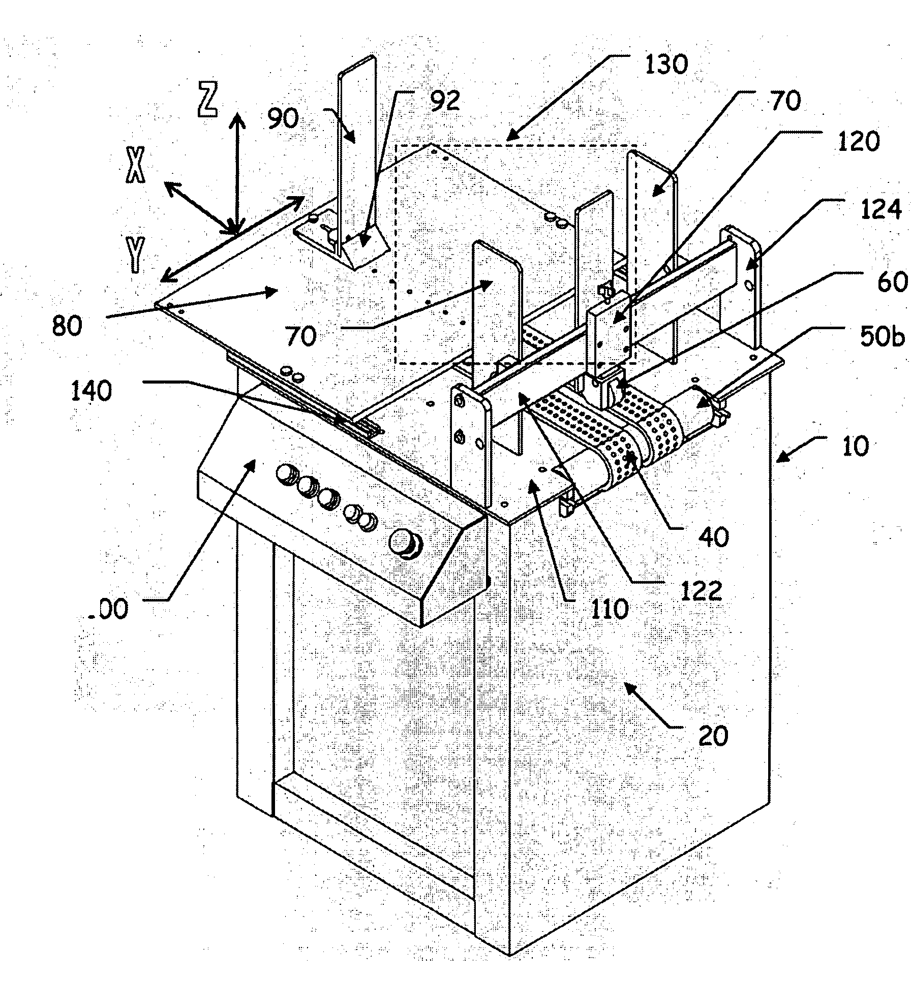
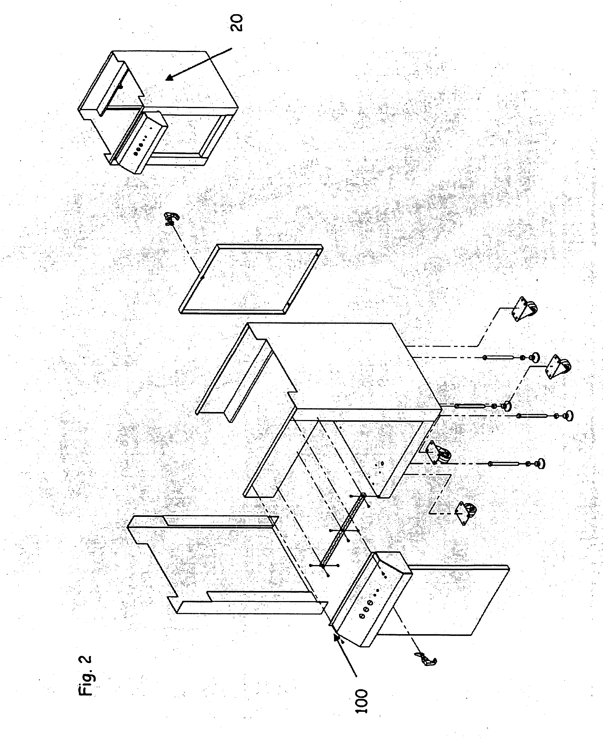
[0022]FIG. 1 shows an exemplary floor model bottom-feed vacuum friction feeder 10 in accordance with the invention. The feeder 10 comprises an enclosure 20 (i.e., a cabinet), at least one and preferably two or more parallel vacuum friction belts 40, a pair of rollers 50a, 50b (see also FIG. 4) for supporting the vacuum friction belt(s) 40, a separator 60, a pair of opposing product side guides 70, an exposure table 80, at least one product back support 90, an operator control panel 100, a ported table top 110, a separator adjuster assembly 120, a hopper area 130 and an exposure table slide adjuster 140. FIG. 4 shows that the table subassembly has a drive motor 30, which drives (i.e., rotates) the vacuum friction belt(s).

[0023]Superimposed on FIG. 1 is an X-axis, which extends toward and away from the separator 60 in a plane defined by the top surface of the exposure table 80. Preferably the top surface of the exposure table 80 is horizontal and parallel to the floor space supporting...


PUM


Abstract

A vacuum friction feeder including at least one vacuum friction belt provided with a plurality of holes, a pair of rollers, a table top provided with at least one suction port, an exposure table having a substantially horizontal top surface and a separator. The at least one vacuum friction belt is adapted to rotate around the table top while supported by the rollers such that a suction pressure can be drawn through the plurality of holes provided in the at least one vacuum friction belt as the plurality of holes pass over the suction port. The exposure table is operatively associated with the table top and is adapted to be movable relative to the table top in a plane defined by the substantially horizontal top surface to adjust the portion of the bottommost product in the stack of products exposed to the at least one vacuum friction belt.

Description

CROSS-REFERENCE TO RELATED APPLICATIONS[0001]This application is a non-provisional of U.S. Provisional Application Ser. No. 61 / 023,653, filed Jan. 25, 2008.BACKGROUND OF INVENTION[0002]1. Field of Invention[0003]The present invention generally relates to a material handling device and, more particularly, to a vacuum friction feeder.[0004]2. Description of Related Art[0005]Bottom-feeding friction feeders are used to individually remove flat stock from the bottom side of a stack and sequentially feed the flat stock into another device such as, for example, a printer, a labeler, a dryer, a collator, a folder or an inserter. Conventionally, the stack of flat stock is positioned such that a portion of the bottom sheet is exposed at an angle to one or more rotating rubber belts. By adjusting factors such as the angle of the stack relative to the belts (which is also known as the “wedge”), the speed of the belts etc., it is possible to sequentially draw a sheet of flat stock from the stack...

Claims


Application Information

Patent Timeline
Patent Type & Authority Applications(United States)
IPC IPC(8): B65H5/02
CPCB65H1/06B65H2405/1116B65H3/56B65H3/126
Inventor WALLACE, ROBERT BRIAN
Owner WALLACE ROBERT BRIAN
Learn More