Wind turbine anemometry compensation
a wind turbine and anemometer technology, applied in the direction of volume metering, machines/engines, instruments, etc., can solve the problems that other conventional nacelle wind speed error correction techniques fail to adequately account for the turbulent effect of the blades
- Summary
- Abstract
- Description
- Claims
- Application Information
AI Technical Summary
Problems solved by technology
Method used
Image
Examples
Embodiment Construction
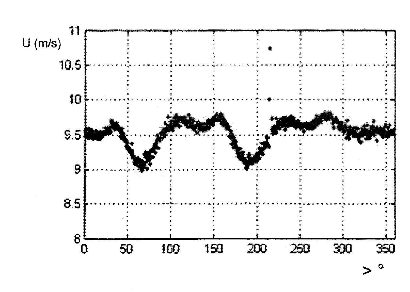
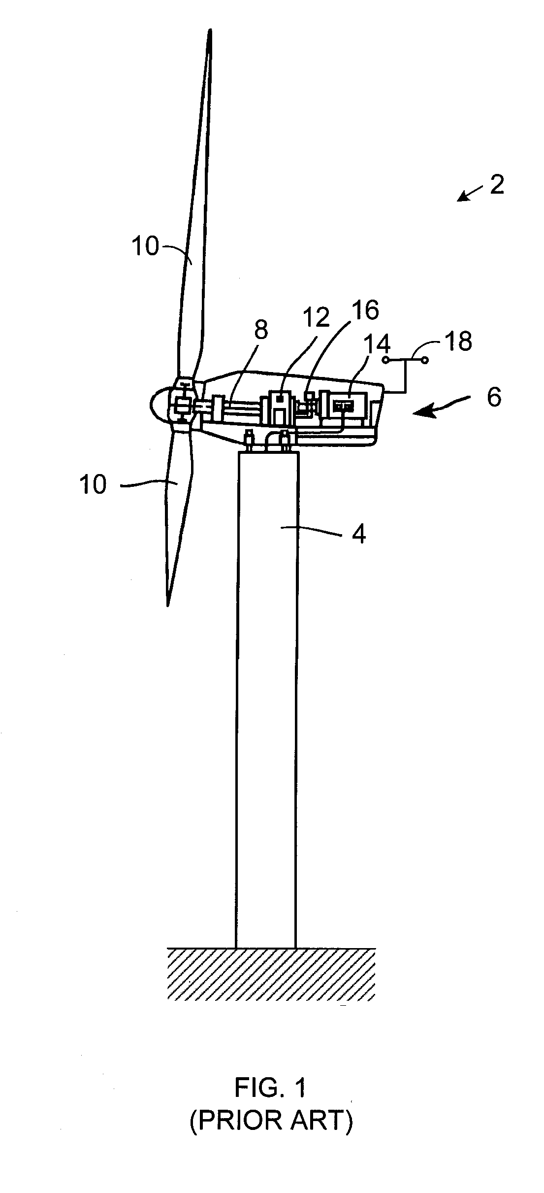
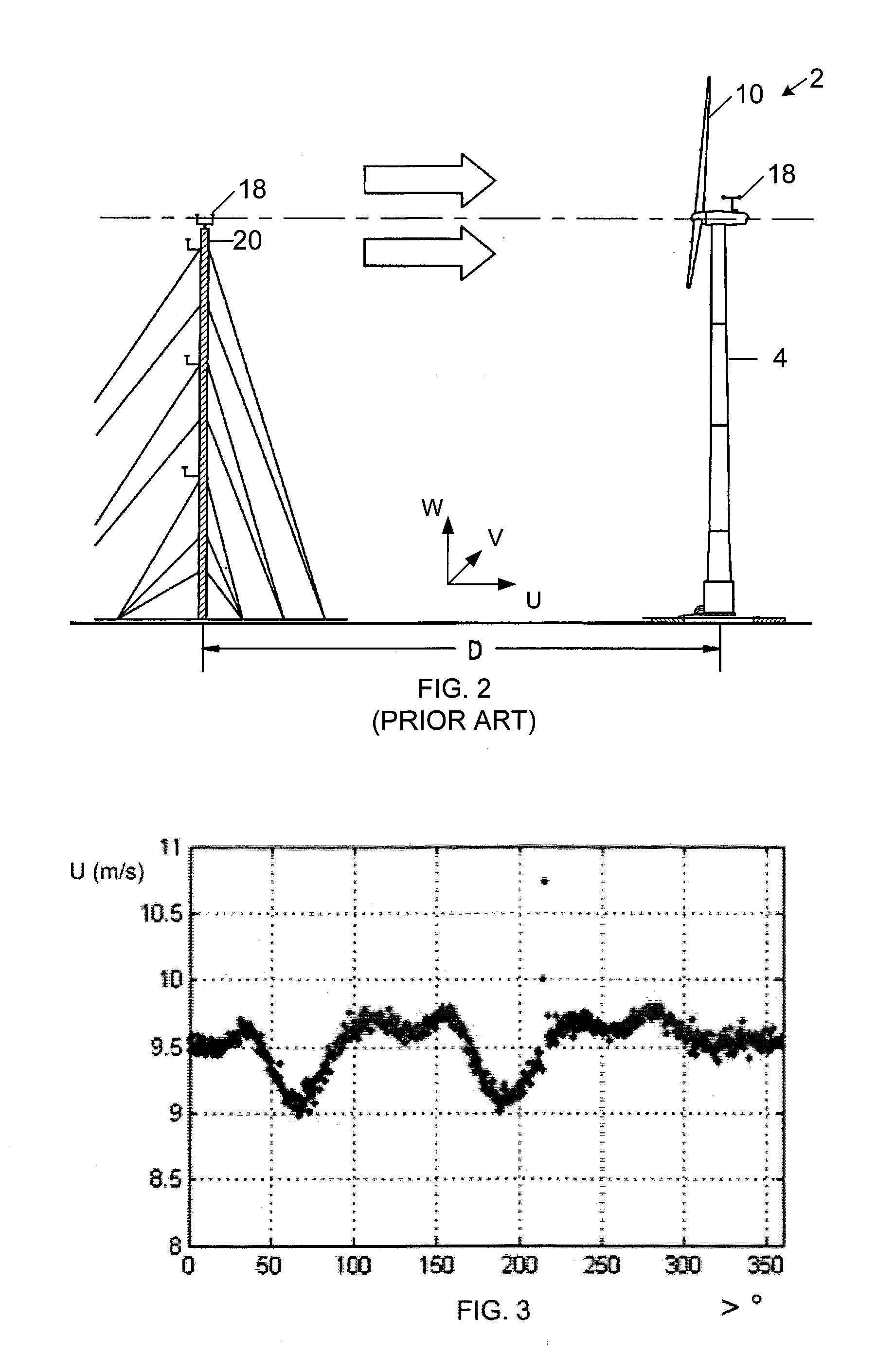
[0025]FIG. 3 is a plot of nacelle wind speed along the rotor axis “U” illustrated in FIG. 2 for average axial wind speeds between nine and ten meters per second. More specifically, the plot shows the nacelle wind speed measured with a three-dimensional, sonic recording anemometer along the axis of the rotor as a function of the angular position of the rotor for measurements falling into a “bin” value of between nine and ten meters per second (“m / s”) along the rotor axis “U” in FIG. 2. However, other anemometers and / or spatial orientations may also be used. FIGS. 4 and 5 show similar plots of average wind speed measurements along the lateral and upward axes, “V” and “W,” identified in FIG. 2 for the same axial wind speed “U” bin of nine to ten m / s. Since the rotor axis “U” may be pitched from horizontal, FIG. 6 further illustrates horizontal wind speed measurements “H” for measured axial wind speeds “U” in the nine to ten m / s bin.
[0026]FIG. 7 is a scatter diagram showing measured hor...
PUM
 Abstract
Description
Claims
Application Information
 - R&D
- Intellectual Property
- Life Sciences
- Materials
- Tech Scout
- Unparalleled Data Quality
- Higher Quality Content
- 60% Fewer Hallucinations
Browse by: Latest US Patents, China's latest patents, Technical Efficacy Thesaurus, Application Domain, Technology Topic, Popular Technical Reports.
© 2025 PatSnap. All rights reserved.Legal|Privacy policy|Modern Slavery Act Transparency Statement|Sitemap|About US| Contact US: help@patsnap.com


