Gas amount measurement device

Active Publication Date: 2009-07-16
JAPAN ATOMIC ENERGY AGENCY INDEPENDANT ADMINISTRATIVE CORP +1
View PDF9 Cites 1 Cited by
  • Summary
  • Abstract
  • Description
  • Claims
  • Application Information

AI Technical Summary

Benefits of technology

[0009]It is an object of the present invention to provide a gas amount measurement device capable of measuring an absolute amount of a specific type of gas contained in molten metal or attached to an inclusion and more accurately grasping characteristics of an obtained product.
[0011]The present invention can provide a gas amount measurement device capable of measuring an absolute amount of a specific type of a gas contained in molten metal or attached to an inclusion and more accurately grasping characteristics of an obtained product.

Problems solved by technology

However, the melting of the refined component again undesirably causes a cost hike.
Due to this, if the used aluminum product is cast in a mold, bubbles disadvantageously remain in an obtained product and pinholes or the like undesirably occur in the obtained product.
However, with the technique disclosed in Jpn. Pat. Appln. KOKAI Publication No. 2003-83865, the measurement device can only measure the total amount of all the gases present, but not individual gases.

Method used


Image

  • Gas amount measurement device
  • Gas amount measurement device
  • Gas amount measurement device

Examples


first embodiment

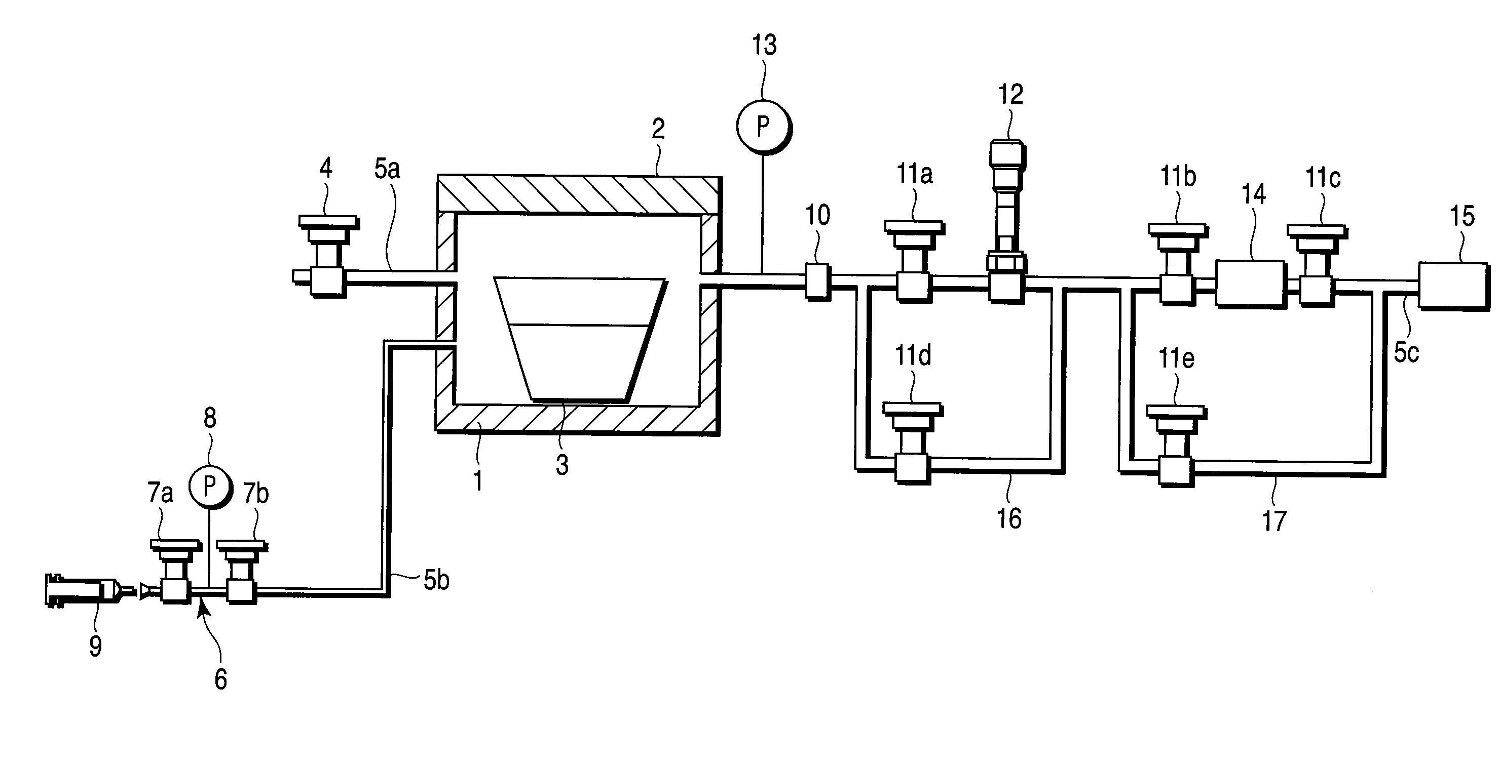
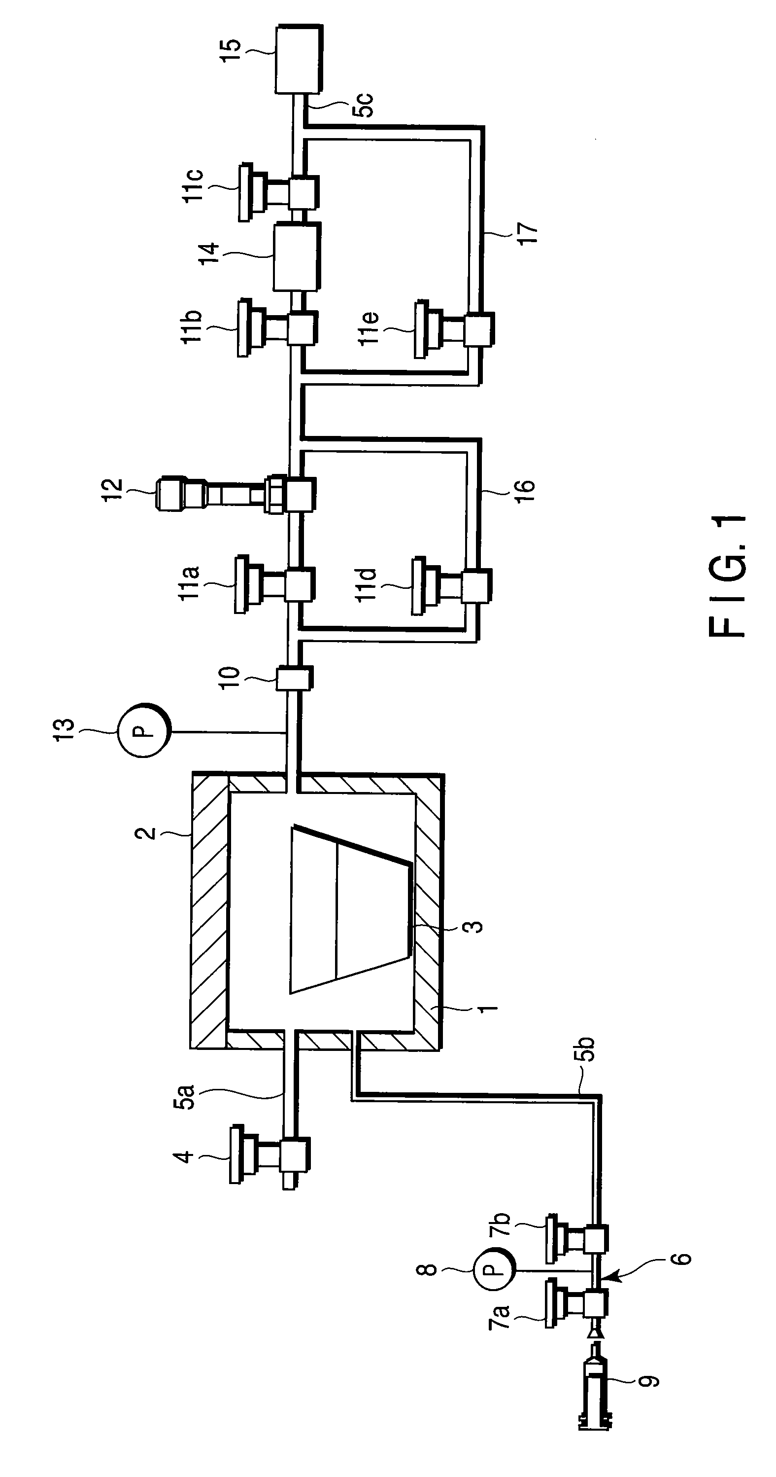
[0021]Referring to FIG. 1, reference symbol 1 denotes a vacuum container including a freely opening / closing cover 2. A sample cup 3 containing therein molten metal (not shown) serving as a sample is arranged in the vacuum container 1. A first pipe 5a, to which an air release valve 4 is attached, is connected to an upstream side of the vacuum container 1. A second pipe 5b, to which a calibration gas generator 6 is attached, is connected to the upstream side of the vacuum container 1. The calibration gas generator 6 is configured to include calibration valves 7a and 7b, a manometer 8 connected to the pipe 5b between the valves 7a and 7b, and a cylinder 9. The internal pressure of the pipe 5b (pipe portion) between the valves 7a and 7b of the calibration gas generator 6 is regulated to an air pressure of 1 atom at the time of flowing the calibration gas.

[0022]A third pipe 5c is connected to a downstream side of the vacuum container 1. A vacuum gauge 13 measuring the internal pressure o...

second embodiment

[0034]Referring to FIG. 4, a gas amount measurement device according to a second embodiment will be described. The same constituent elements shown in FIG. 4 as those shown in FIG. 1 are denoted by the same reference symbols and will not be described herein. The second embodiment is characterized, as compared with the first embodiment shown in FIG. 1, in that a heater 21 is provided around the sampling cup 3.

[0035]According to the second embodiment, temperature fall of the molten metal contained in the sample cup 3 can be suppressed by presence of the heater 21.

[0036]The present invention is not limited to the first and second embodiments but can be carried out by modifying the constituent elements within the scope of the invention. Furthermore, various inventions can be created by appropriate combinations of a plurality of constituent elements disclosed in the first and second embodiments. For example, several constituent elements can be eliminated from all the constituent elements ...


PUM


Abstract

A gas amount measuring device including a vacuum container, a first pipe, an air release valve being attached to the first pipe, a second pipe, a calibration gas generator being attached to the first pipe, a third pipe, a vacuum gauge, a first valve, a leak valve, a second valve, a turbomolecular pump, a third valve, and a roughing pump being attached to the third pipe in order from a vacuum container side, a first bypass pipe connecting the third pipe between the vacuum container and the first valve to the third pipe between the leak valve and the second valve, a fourth valve being attached to the first bypass pipe, and a second bypass pipe connecting the third pipe between the leak valve and the second valve to the third pipe between the third valve and the roughing pump, a fifth valve being attached to the second bypass pipe.

Description

CROSS-REFERENCE TO RELATED APPLICATIONS[0001]This application is based upon and claims the benefit of priority from prior Japanese Patent Application No. 2008-006205, filed Jan. 15, 2008, the entire contents of which are incorporated herein by reference.BACKGROUND OF THE INVENTION[0002]1. Field of the Invention[0003]The present invention relates to a gas amount measurement device. More specifically, the present invention relates to a gas amount measurement device for measuring an entire amount of gas contained in molten metal or an amount of gas attached to an inclusion.[0004]2. Description of the Related Art[0005]Conventionally, a specific metal or alloy is used for a component such as a vehicle engine. Meanwhile, it is generally known that an amount of impurity gas per unit weight after refining a component is smaller than that before refining. This is because the impurity gas contained in a sample, that is, the component vaporizes during refining. In such a case, the refined comp...

Claims


Application Information

Patent Timeline
IPC IPC(8): G01N33/20G01N7/00
CPCG01N7/14
Inventor ABE, TETSUYAHATANO, TOSHIHISAHIRATSUKA, HAJIMEHASEGAWA, KOICHITAJIMA, YASUHIDEOMACHI, SOICHIRO
Owner JAPAN ATOMIC ENERGY AGENCY INDEPENDANT ADMINISTRATIVE CORP
Why Eureka
Try Eureka