
Method of interpolation between a plurality of observed tensors

a plurality of observed tensors and interpolation method technology, applied in the field of improved methods, can solve the problems of high cost of data gathering process using airborne sensors, insufficient information use, and methods that are far too slow to be useful for the volume of data involved in geophysical surveys, especially airborne geophysical surveys

Active Publication Date: 2009-07-09
DESMOND FITZGERALD & ASSOCS
View PDF1 Cites 11 Cited by
  • Summary
  • Abstract
  • Description
  • Claims
  • Application Information

AI Technical Summary

Benefits of technology

"The present invention provides a method for interpolating field gradient data between two observed data sets. The method involves decomposing the field gradient data into rotational and structural matrices, separately interpolating each component, and recombining them to reconstruct the original field gradient tensor at the interrelation points in space. The method allows for the separation of structural and rotational information, provides an optimal way of resampling on to regular spaced intervals in preparation for fast fourier transform operations, and highlights inadequate data quality. The method can be used during gridding, resampling, and visualization of field gradient data."

Problems solved by technology

The data gathering process using airborne sensors is very expensive.
However, present methods do not make the best use of the information and there is a need for improved estimation and visualisation of geological features.
As gatherers of data are unaware that much of the noise of the signal reports in the rotational component, they may neglect to gather the full gradient data in the first place.
While the separation of structural and rotational tensors can be obtained by hand using graphical methods such as “Mohr's Circles” which are well known in the rock mechanics field, those methods are far too slow to be useful for the volumes of data involved in geophysical surveys, especially airborne geophysical surveys.

Method used


Image

  • Method of interpolation between a plurality of observed tensors
  • Method of interpolation between a plurality of observed tensors

Examples


Embodiment Construction

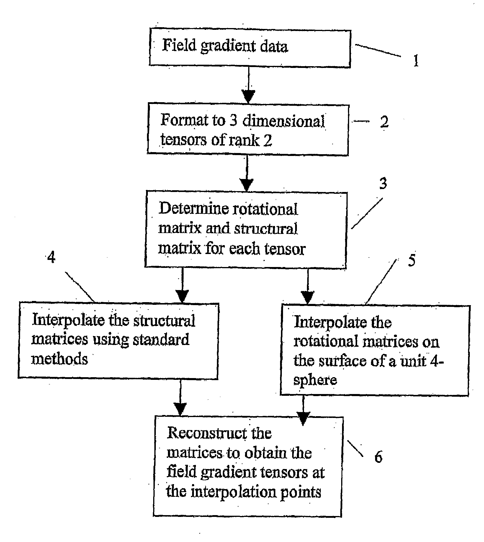
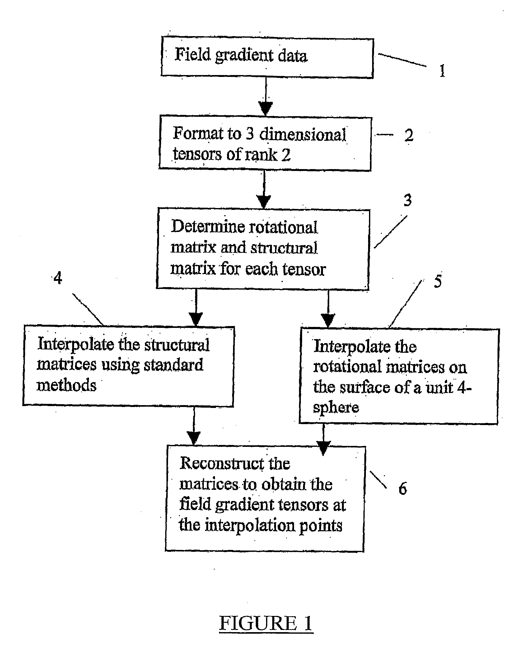
[0081]In order that the invention may be more clearly understood, a preferred non-limiting embodiment is described by reference to the accompanying FIG. 1.

[0082]FIG. 1 is a flow diagram outlining the steps in performing a preferred embodiment of the invention.

[0083]In step 1 the field gradient data, provided, for example, by an aerial geophysical field gradient survey, is accessed and in Step 2 is converted into a preferred predetermined format being 3-dimensional tensors of rank 2. The field gradient tensors are expressed as 3×3 matrices. Each of these matrices is resolved by predefined mathematical techniques into a rotational matrix and a structural matrix in Step 3. Each rotational matrix and each structural matrix has three diagonal components or eigen values.

[0084]The structural matrices are interpolated using standard mathematical techniques. As the structural matrices are independent of the choice of coordinate systems, they can be interpolated or filtered conventionally on ...


PUM


Abstract

A method of interpolation between a plurality of field gradient tensors including the steps of:accessing a plurality of field gradient data;formatting said plurality of field gradient data into 3-dimensional tensors of rank 2;determining a rotational matrix and a structural matrix for each tensor;interpolating said structural matrices;detecting errors in the raw data only apparent using the rotational component.interpolating said rotational matrices as quaternions on the surface of a unit 4-sphere;reconstructing said structural matrices and said rotational matrices to yield field gradient tensors at the interpolation points, wherein the interpolation is between two said field gradient tensors, the field gradient tensors being expressed as 3×3 matrices of values, each resolved into a rotational matrix and a structural matrix with three diagonal components.

Description

[0001]This application is a National Stage of International Application PCT / AU2007 / 000066 filed Jan. 24, 2007. Applicant claims foreign priority benefits under 35 U.S.C. 119(a)-(d) of the following foreign application for patent: Australian Application No. 2006900346, filed Jan. 24, 2006, which is hereby incorporated by reference in its entirety.FIELD OF THE INVENTION[0002]This invention relates to interpolation between gravity, electro-magnetic and possibly other field gradient data sets. In particular this invention relates to an improved method of interpolation between field gradient data sets, including an improved method of interpolation between a plurality of observed field gradient tensors.BACKGROUND OF THE INVENTION[0003]Geophysical field gradient surveys generally are conducted by using line scans which give results along that line. Where an area is to be surveyed a number of line scans, preferably parallel, are made and interpolations of data between those line scans are m...

Claims


Application Information

Patent Timeline
Patent Type & Authority Applications(United States)
IPC IPC(8): G01V3/38G01V7/06G01V1/28
CPCG01V11/00G01V3/38
Inventor FITZGERALD, JAMES DESMONDHOLSTEIN, HORST
Owner DESMOND FITZGERALD & ASSOCS
Learn More