
Devices and methods for treating pelvic floor dysfunctions

a technology for pelvis and pelvis, applied in the field of medical devices, can solve the problems of increased prolapse recurrence risk, increased risk of prolapse recurrence, and insufficient surface area of sutures

Active Publication Date: 2009-07-02
BOSTON SCI SCIMED INC
View PDF103 Cites 132 Cited by
  • Summary
  • Abstract
  • Description
  • Claims
  • Application Information

AI Technical Summary

Benefits of technology

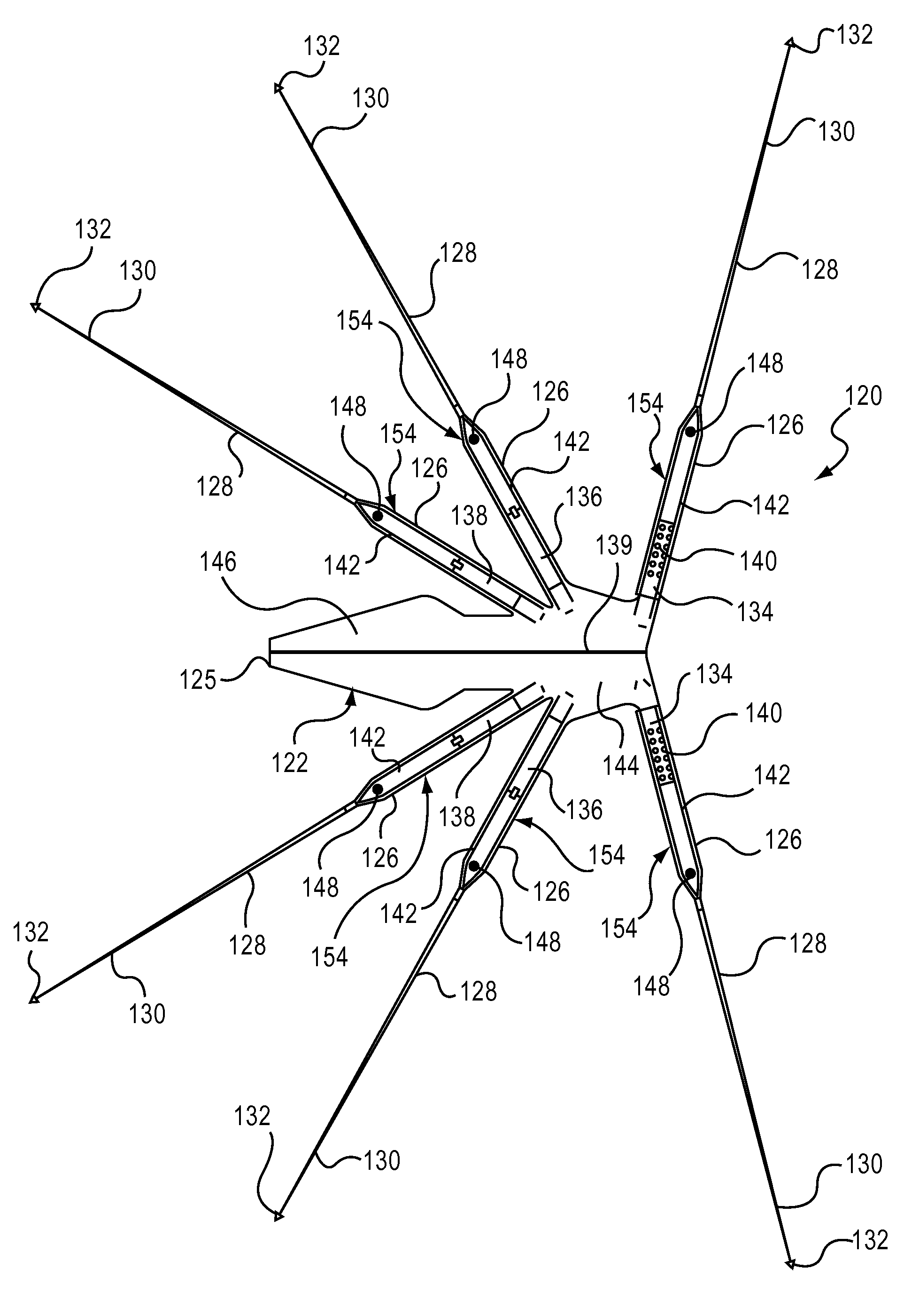
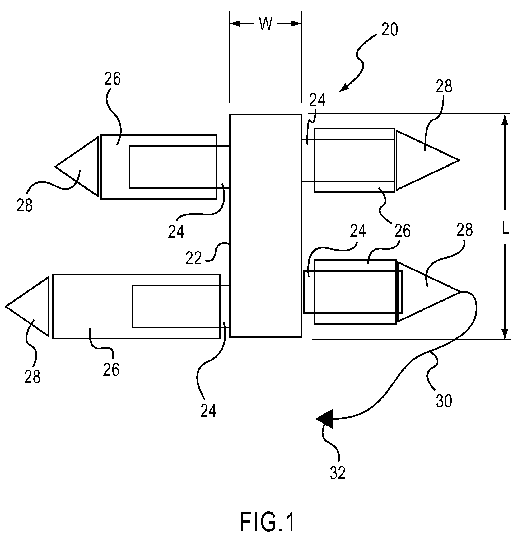
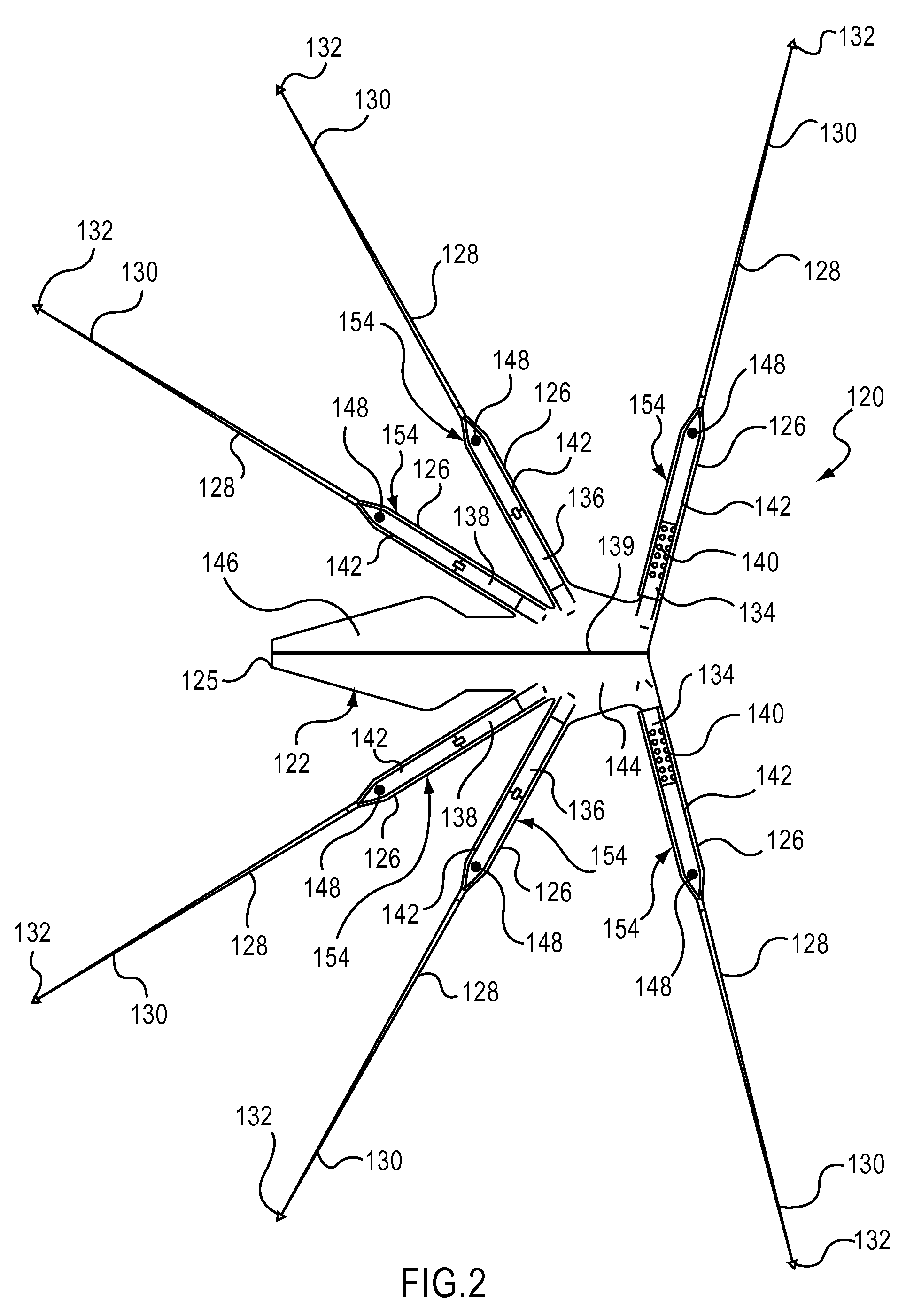
The patent describes an apparatus for use in a pelvic region that includes a support portion and a strap with a sleeve. The strap is placed within the pelvic tissue and the sleeve is placed over at least a portion of the strap. The sleeve is longer than the strap and is attached to it with a suture. The apparatus may also have a suture within the sleeve with two separate strands. The technical effect of this invention is to provide a better support and protection for the pelvic region during medical procedures.

Problems solved by technology

For example, if an implant is too large for the particular patient, damage to surrounding tissue can occur.
In some cases, an implant that is too small can increase the chance of prolapse recurrence.
Sutures may not provide enough surface area for tissue in-growth, and may require knotting in order to be secured.
Various complications can occur during a procedure to deliver and secure a pelvic implant due to, for example, space constraints for performing the implantation procedure.
Often, implants can become damaged during delivery due to the type of delivery device and / or the type of implant, or due to excessive handling of the implant during the implant procedure.

Method used


Image

  • Devices and methods for treating pelvic floor dysfunctions
  • Devices and methods for treating pelvic floor dysfunctions
  • Devices and methods for treating pelvic floor dysfunctions

Examples


Embodiment Construction

[0060]The devices and methods described herein are generally directed to implants (e.g., posterior support implants, anterior support implants, total pelvic floor repair implants) and the delivery and placement of such implants within a pelvic region (also referred to herein as “pelvis”) of a patient. An implant can be placed into the pelvic space of a patient and secured at several different locations within the pelvic space to treat many different female pelvic floor dysfunctions. For example, an implant can be secured to a sacrospinous ligament or a ureterosacral ligament for uterine preservation (e.g., if a prolapsed uterus is otherwise healthy, a hysterectomy is not preformed and the uterus is re-suspended with an implant), or for posterior support. In another embodiment, an implant can be secured to pubo-urethral tissue or an obturator muscle (e.g., internus or externus) or membrane (each also referred to herein as “obturator”) to treat, for example, incontinence. In yet anoth...


PUM


Abstract

In one embodiment, an apparatus includes a support portion disposable within a pelvic region and a strap extending from the support portion. The strap has a length and is configured to be disposed at least partially within a pelvic tissue. A sleeve is releasably disposed over at least a portion of the strap. The sleeve has a length that is longer than the length of the strap. In some embodiments, the length of the sleeve is at least twice as long as the length of the strap. In some embodiments, a suture couples the sleeve to the strap. The apparatus can also include a suture disposed at least partially within an interior of the sleeve and forming two strands of suture within the interior of the sleeve. The two strands are separated by a distance defined by a separator portion of the sleeve.

Description

CROSS-REFERENCE TO RELATED APPLICATIONS[0001]This application claims priority to U.S. Provisional Patent Application Ser. No. 61 / 017,212, entitled “Devices and Methods for Treating Pelvic Floor Dysfunctions,” filed Dec. 28, 2007, the disclosure of which is hereby incorporated by reference in its entirety.BACKGROUND[0002]The disclosed invention relates generally to medical devices and more particularly to implants and methods for delivering implants within a pelvic region of a patient to treat various pelvic dysfunctions.[0003]A variety of medical procedures are performed to treat various female pelvic dysfunctions, including procedures to treat urinary incontinence, and correcting various prolapse conditions such as uterine prolapse, cystoceles, rectoceles, and vaginal vault prolapse.[0004]Women often experience vaginal prolapses due to age or other factors. For example, women may experience a cystocele, a rectocele and / or a hysterocele. A cystocele occurs when the bladder bulges in...

Claims


Application Information

Patent Timeline
Patent Type & Authority Applications(United States)
IPC IPC(8): A61F2/02A61F2/04
CPCA61B17/0401A61B17/0482A61B17/0485A61B17/06109A61F6/08A61B2017/06042A61F2/0045A61F2/0063A61B2017/00805
Inventor CHU, MICHAEL S. H.
Owner BOSTON SCI SCIMED INC
Learn More