
Display device

a display device and thin-screen technology, applied in the field of display devices, can solve the problems of large shield member sizes, large number of electronic parts, and thin thin-screen display devices, and achieve the effect of facilitating product inspection and maintenan

Inactive Publication Date: 2009-07-02
ORION ELECTRIC CO LTD
View PDF3 Cites 16 Cited by
  • Summary
  • Abstract
  • Description
  • Claims
  • Application Information

AI Technical Summary

Benefits of technology

"The present invention provides a display device that facilitates product inspection and maintenance, and enables shield members to be appropriately applied in places where noises are generated. The display device includes an internal component parts mounting portion on the back cabinet, a placement portion for placing the display panel, and a holding portion for holding the display panel in a standing manner. The display panel can be easily connected to the circuit board and other components within the cabinet. The display device also includes a shield member for suppressing the effect of noises generated by the circuit board. Overall, the display device provides improved manufacturing and maintenance capabilities, as well as improved noise reduction."

Problems solved by technology

Because thin-screen display devices are very thin compared to conventional display devices, a large number of electronic parts are incorporated at high densities.
Although the method of Japanese Patent Laid-Open Publication No. 6-252567 is readily applied to small display devices in which electronic parts are densely packed in a surrounding manner, the sizes of the shield members become large when this method is applied to relatively large display devices, such as television receiving sets and personal computers used in general households, and it is difficult to avoid rises in manufacturing costs and increases in weight.
Also in the method of Japanese Utility Model Registration Publication No. 3127049, rises in manufacturing costs and increases in weight occur similarly due to the increase in the sizes of the shield members.
Therefore, during the performance inspection and maintenance of products, when the circuit boards and the like are checked, it is necessary to detach the front frame and the back frame, and furthermore the back-side shield member, thereby making the work complicated.

Method used


Image

  • Display device
  • Display device
  • Display device

Examples


Embodiment Construction

[0043]A preferred embodiment for carrying out the present invention will be described below with reference to FIGS. 1 to 14. Of course, it is needless to say that the present invention can be readily applied to embodiments of other constitutions other than those described in the embodiment so long as these do not depart from the gist of the present invention.

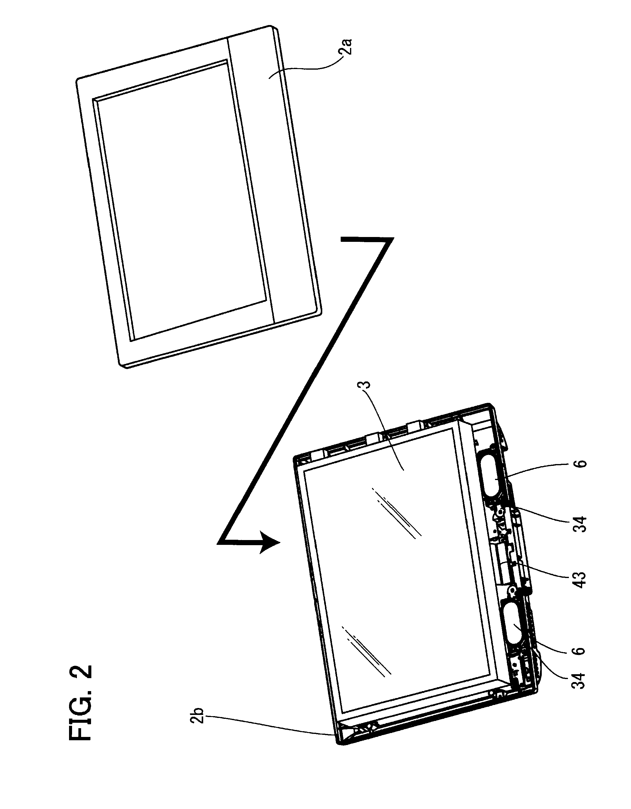
[0044]FIG. 1 is a perspective view of a video display device in an embodiment of the present invention. FIG. 2 is an exploded perspective view of the video display device, in which a front cabinet of the video display device is removed. FIG. 3 is a perspective view of the video display device, in which a display panel is removed from a back cabinet.

[0045]An example of a display device shown in FIGS. 1 to 3 is a display device 1, such as a thin-screen liquid-crystal television receiving set having a small depth dimension. A resin cabinet 2 that forms the appearance of the display device 1 is composed of a front cabinet 2a and a b...


PUM


Abstract

The present invention provides a display device that facilitates product inspection and maintenance. A button section is mounted to a back cabinet, and a power-source circuit board is fitted into a circuit-board fitting slit. Furthermore, the power-source circuit board is locked and fixed by a first circuit-board locking claw, and a main circuit board is locked and fixed by a second circuit-board locking claw. A speaker integrally assembled in a speaker holder is locked and fixed by a speaker locking claw, and thereafter a display panel is caused to be held by a display panel standing holding portion in a standing manner. The wire connection work of a display panel, each of the circuit boards, and the like is performed, the display panel is brought down and placed on a display panel placement portion, a front cabinet is mounted, and a leg portion is mounted to a leg-portion mounting portion.

Description

[0001]The present application is based on and claims priority of Japanese patent application No. 2007-339297 filed on Dec. 28, 2007, the entire contents of which are hereby incorporated by reference.BACKGROUND OF THE INVENTION[0002]1. Field of the Invention[0003]The present invention relates to a display device having high workability in manufacture and maintenance.[0004]2. Description of the Related Art[0005]Thin-screen display devices have predominant market shares in recent display devices, and the percentage of thin-screen display devices has been increasing year by year. Because thin-screen display devices are very thin compared to conventional display devices, a large number of electronic parts are incorporated at high densities. Therefore, it is necessary to perform shielding strictly in order to prevent noises generated from circuit boards and electronic parts from affecting other circuit boards.[0006]For example, in a liquid-crystal display panel used in a pachinko board wh...

Claims


Application Information

Patent Timeline
Patent Type & Authority Applications(United States)
IPC IPC(8): H05K5/02G06F1/16H04N5/64
CPCG06F1/1601H05K9/0054H05K5/02H04N5/64
Inventor KATAOKA, YUSUKEMUKOUGAWA, HIDENOBUMOROISHI, MASAHIDEOHKUBO, SEIGOTANIKAWA, SHINICHIMAENO, TAKANORISAGA, YOSHIKAZUTSUBOTA, KENJIMITAMURA, TAMOTSU
Owner ORION ELECTRIC CO LTD
Learn More