Stud connector and related methods

a technology of connecting rods and studs, which is applied in the direction of transformer/coil connectors, electrical equipment, connections, etc., can solve the problems of affecting the conduction of electricity from the stud to the conductor, the loss of connectivity, and the inability to compensate for the loss of connectivity by threading the stud within the bor

Inactive Publication Date: 2009-06-25
ILSCO
View PDF19 Cites 16 Cited by
  • Summary
  • Abstract
  • Description
  • Claims
  • Application Information

AI Technical Summary

Benefits of technology

[0007]These and other problems in the prior art have been addressed with this invention. In one embodiment, a connector for connecting a transformer stud with at least one conductor includes first and second opposed end faces, with each of the faces respectively including first and second ports configured to receive the stud therethrough. A central bore extends from at least the first port for receiving the stud therein. The connector includes a plurality of channels oriented transverse to the central bore with each of the channels being configured to receive a conductor therein. The central bore may extend from the first port to the second port. The central bore may be configured to selectively receive studs of at least two different sizes. The central bore may be configured to selectively receive studs, for example, having respectively diameters of about ⅝ of an inch and about 1 inch. The central bore may include an extruded toothed surface configured to secure the stud there against. The central bore may define a ce...

Problems solved by technology

Connectors of the type described above have other limitations.
For example, the threadable coupling of the stud within the bore does not compensate for the loss of connectivity caused by oxidation formed on threads of the stud.
Hence, conduction of electricity from the stud to the conduc...

Method used


Image

  • Stud connector and related methods
  • Stud connector and related methods
  • Stud connector and related methods

Examples


Embodiment Construction

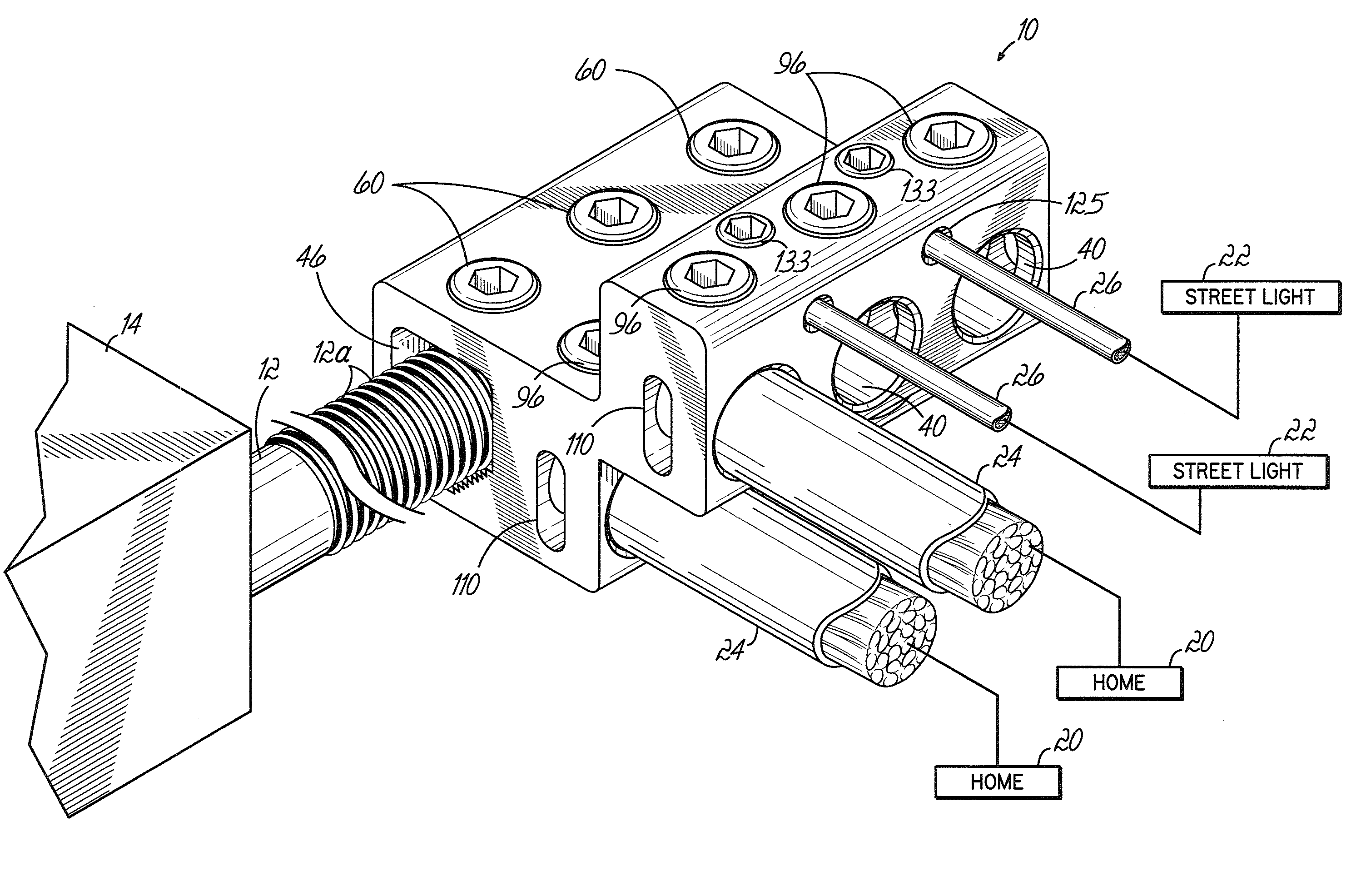
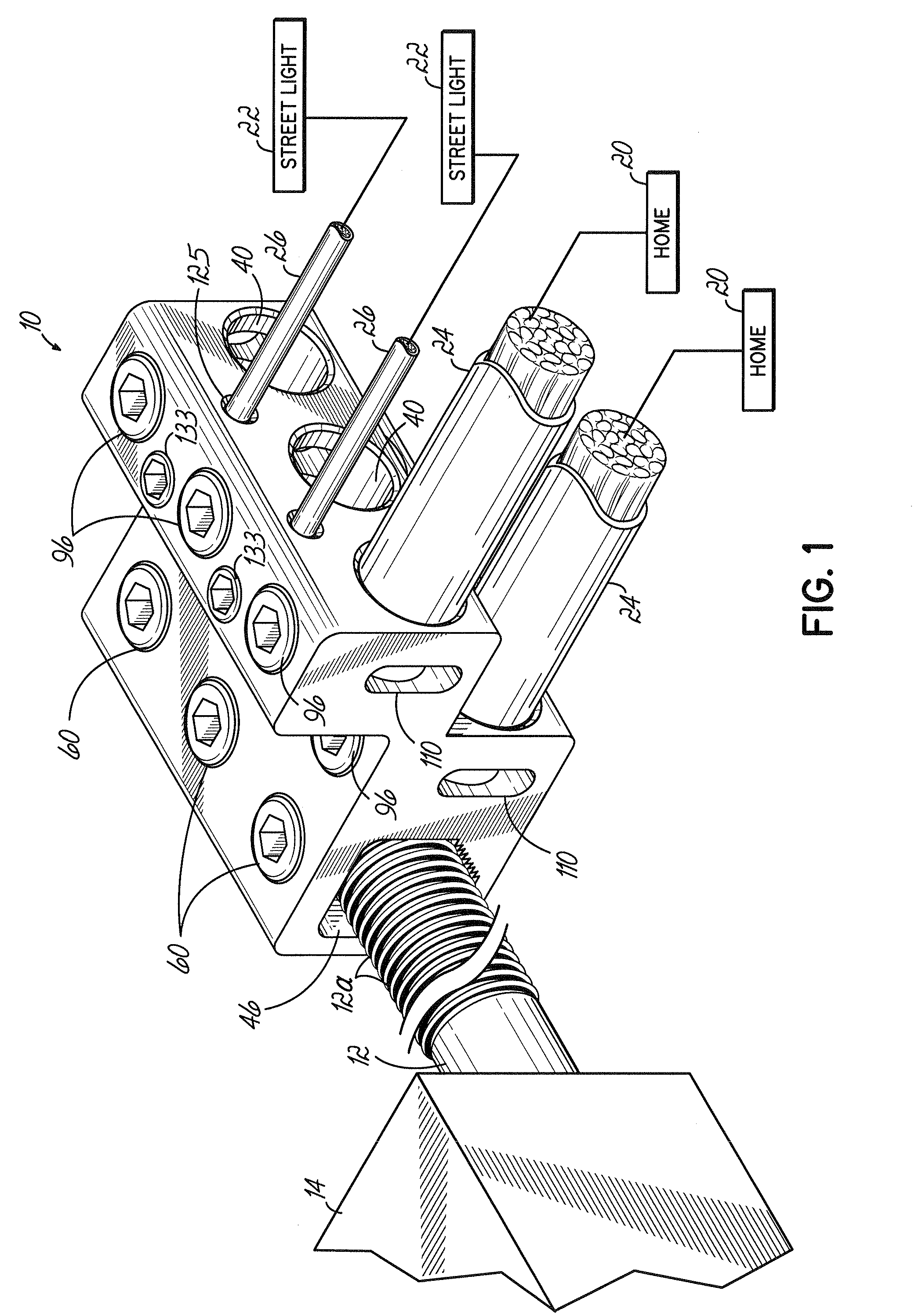
[0026]With reference to the drawings and, more particularly to FIG. 1, a connector 10 is depicted connecting a stud 12 of a transformer 14 for conveying electric power to multiple power-consuming devices or systems. The connector 10 may, for example, convey electric power to homes 20 and street lights 22. In this exemplary embodiment, the connector 10 conveys electric power to homes 20 and street lights 22 respectively through conductors 24, 26 coupled to the connector 10.

[0027]With reference to FIGS. 1-2, the connector 10 in this illustrative embodiment is a generally Z-shaped structure having first and second body portions 30, 32, each of which is configured to connect to at least three conductors 24. To this end, each body portion 30, 32 includes three channels 40, each configured to accept a solid or stranded conductor 24 therein, as explained in further detail below.

[0028]Connection to the stud 12 is facilitated by at least one central bore 46 disposed within the first body por...


PUM


Abstract

A connector for connecting a transformer stud with at least one conductor includes first and second opposed end faces, with each of the faces respectively including first and second ports configured to receive the stud therethrough. A central bore extends from at least the first port for receiving the stud therein. The connector includes a plurality of channels oriented transverse to the central bore with each of the channels being configured to receive a conductor therein. The central bore may extend from the first port to the second port. The central bore may be configured to selectively receive studs of at least two different sizes. The central bore may be configured to selectively receive studs, for example, having respectively diameters of about ⅝ of an inch and about 1 inch. The central bore may include an extruded toothed surface configured to secure the stud there against.

Description

FIELD OF THE INVENTION[0001]This invention relates to electrical connectors and, more particularly, to connectors to connect transformer studs to conductors.BACKGROUND OF THE INVENTION[0002]Various types of electrical connectors are used for connecting electrical conductors to one another or to the terminals of electrical devices. Conventional connectors receive a conductor within a channel or the like and then receive a screw. The screw is then tightened against the conductor so that it is held in physical contact with the connector.[0003]Some connectors are used with transformers having one or more studs, which provide a high voltage, for example, to a group of homes. Connectors of this type connect the stud to several conductors, each leading to a home. Conventional connectors of this type may include a single port defining a bore that receives the stud, with the bore having a machined surface for threadably securing the stud. Connectors of this type may be available in right-han...

Claims


Application Information

Patent Timeline
IPC IPC(8): H01R11/11
CPCH01R4/26H01R2201/22H01R9/2408H01R4/36
Inventor SWEENEY, THOMAS M.TAYLOR, CARL J.
Owner ILSCO
Why Eureka
Try Eureka