
Hearing device, hearing device system and method of controlling the hearing device system

a hearing device and hearing technology, applied in the direction of deaf-aid sets, electrical equipment, deaf input selection/mixing, etc., can solve the problems of user discomfort and unpleasing noise, and achieve the effects of improving the handling of hearing devices, effective inhibition, and increasing comfort for users

Inactive Publication Date: 2009-06-18
OTICON
View PDF9 Cites 23 Cited by
  • Summary
  • Abstract
  • Description
  • Claims
  • Application Information

AI Technical Summary

Benefits of technology

[0063]An advantage of the present invention is to provide a scheme for use of a hearing instrument or a pair of hearing instruments together with a telephone (e.g. a mobile telephone), which is more comfortable since on the one hand the undesired feedback is effectively inhibited and on the other hand no further manual operation or setting is necessary. The performance of the hearing device system according to the present invention therefore provides an increased comfort for the user and an improved handling of the hearing devices while the occurrence of the feedback is suppressed without reducing operability of the system. The interaction between the hearing devices and the telephone handset is improved and facilitated for the user. Hence, it is easy for the user of the hearing device system to wear the hearing devices even when the user receives a telephone call or when a telephone call is intended by the user.
is to provide a scheme for use of a hearing instrument or a pair of hearing instruments together with a telephone (e.g. a mobile telephone), which is more comfortable since on the one hand the undesired feedback is effectively inhibited and on the other hand no further manual operation or setting is necessary. The performance of the hearing device system according to the present invention therefore provides an increased comfort for the user and an improved handling of the hearing devices while the occurrence of the feedback is suppressed without reducing operability of the system. The interaction between the hearing devices and the telephone handset is improved and facilitated for the user. Hence, it is easy for the user of the hearing device system to wear the hearing devices even when the user receives a telephone call or when a telephone call is intended by the user.

Problems solved by technology

This undesired feedback produces an unpleasing noise which makes the user feel uncomfortable.

Method used


Image

  • Hearing device, hearing device system and method of controlling the hearing device system
  • Hearing device, hearing device system and method of controlling the hearing device system
  • Hearing device, hearing device system and method of controlling the hearing device system

Examples


first embodiment

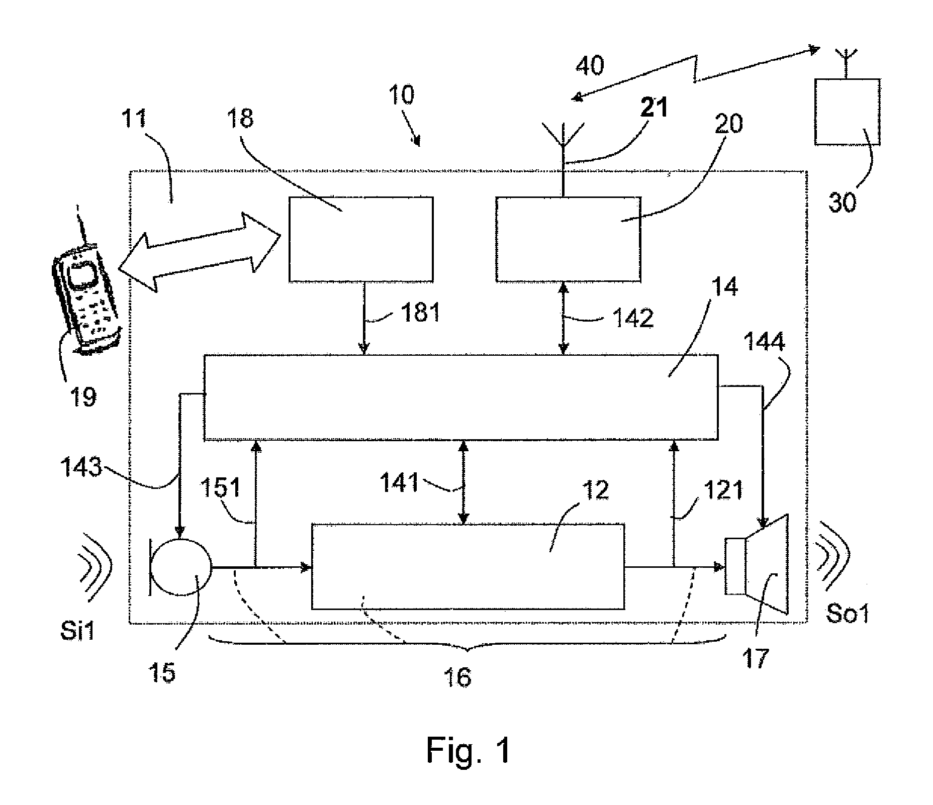
[0071]An embodiment of the present invention is described in the following in conjunction with the schematic diagram shown in FIG. 1.

[0072]In more detail, FIG. 1 shows an overall arrangement of a hearing device 10 according to a first embodiment of the present invention. The hearing device 10 comprises a main body 11 wherein the further means and units of the hearing device are arranged or implemented. In other embodiments, the location of the main components of the hearing device may be arranged in other ways, appropriate for fulfilling the actual physical constraints and functional requirements.

[0073]In the bottom part of the block diagram, the electric signal path 16 between the electric sides of input transducer 15 and output transducer 17 is illustrated. Acoustic input signal Si1 (possibly originating from the speaker of a mobile telephone 19) is picked up by the microphone 15 and converted to an electric input signal 151, which is fed to a processing unit 12 and to a control u...

second embodiment

[0084]The operation of the hearing device 10 as described in conjunction with the first embodiment as well as the interaction of plural hearing devices 10 forming a hearing device system as well as the control concept thereof is described in the following in conjunction with a second embodiment of the present invention. Regarding the second embodiment of the present invention, reference is made to FIGS. 2 and 3.

[0085]FIG. 2 schematically shows the arrangement of a hearing device system, which is composed of at least first and second hearing devices 10, 30 arranged in the manner as described in conjunction with the first embodiment of the present invention. The interaction between these at least two hearing devices 10 and 30 forming the hearing device system as well as the cooperation with the telephone handset 19 as shown in FIG. 2 is described in the following.

[0086]As is roughly shown in FIG. 2, both the first hearing device 10 and the second hearing device 30 are arranged at the ...


PUM


Abstract

The present invention refers to a hearing device system which comprises: at least a first hearing device (10) including a first control unit (14) and a second hearing device (30) including a second control unit (37) for processing acoustic signals. Each of the hearing devices includes a transceiver (20, 34) for establishing a data communications link (40) between the first and the second hearing devices. At least one of the hearing devices including a sensing means (18, 33) for detecting, whether a telephone handset (19) is placed close to the hearing device. Each of the control units includes at least a first and a second control mode. Both hearing devices are adapted for outputting the processed acoustic signals in the first control mode. Upon detection of the telephone handset the first hearing device is shifted to the second control mode for inhibiting the output of the processed acoustic signals and establishing the data communications link for transmitting the processed acoustic signals to the second hearing device. The second hearing device is also shifted to the second control mode for receiving the processed acoustic signals transmitted from the first hearing device and outputting the transmitted acoustic signals.

Description

TECHNICAL FIELD[0001]The present invention refers to a hearing device, a hearing device system and a method of controlling the hearing device system, and specifically to a hearing device system including at least two hearing devices for operation in conjunction with the use of a telephone handset.BACKGROUND ART[0002]A hearing device or hearing aid for an operation in conjunction with a telephone headset to be employed by the user of the hearing aid is known from prior art document US 2006 / 0013420 A1. This document discloses an arrangement including two hearing aids, one of the hearing aids having means for detecting the presence of a telephone handset close to this hearing aid. Specifically, a sensor is provided for detecting the voice coil of the telephone handset when the handset is held close to the user's ear equipped with the respective hearing aid. When both hearing aids are operated in the normal hearing mode which constitutes a microphone mode for amplifying for the user any...

Claims


Application Information

Patent Timeline
Patent Type & Authority Applications(United States)
IPC IPC(8): H04R25/00
CPCH04R25/43H04R25/453H04R2499/11H04R25/554H04R25/552
Inventor RASMUSSEN, KARSTEN BO
Owner OTICON
Learn More