Eureka AIR delivers breakthrough ideas for toughest innovation challenges, trusted by R&D personnel around the world.

Radio network controlling method, radio communication system and radio network controller

a radio network controller and radio communication system technology, applied in power management, wireless communication, wireless commuication services, etc., can solve the problems of radio network controllers not being the base station cannot be able to regulate the use of dpch

Active Publication Date: 2009-06-18
NEC CORP
View PDF3 Cites 17 Cited by
  • Summary
  • Abstract
  • Description
  • Claims
  • Application Information

AI Technical Summary

Benefits of technology

The present invention provides a radio network controlling method, a radio communication system, and a radio network controller that can effectively regulate the use of a downlink dedicated channel and a downlink shared channel for transmitting data to mobile stations. The method and system measure the transmission power and activity ratio of all channels, and use these measurements to calculate the power assigned to the downlink shared channel. The use of the downlink dedicated channel is then regulated based on the assigned power and activity ratio. This approach ensures efficient use of network resources, reduces cell load, and improves overall data transmission performance.

Problems solved by technology

The above described radio network controlling method has a problem in assigning power by the base station and executing admission control by the radio network controller.
Accordingly, even when power assignment to a channel for HSDPA is small, the base station can not regulate use of DPCH.
In addition, without information about total transmission power of the base station or about power assigned to HSDPA, the radio network controller can not regulate use of DPCH.
The conventional radio network controlling methods, however, have the problem that setting a threshold value of admission control to be low results in ensuring power for HSDPA even when no mobile station corresponding to HSDPA exists.
On the other hand, setting a threshold value of admission control to be high to solve the above-described problem invites a problem of reduction in power assigned to a channel for HSDPA.

Method used


Image

  • Radio network controlling method, radio communication system and radio network controller
  • Radio network controlling method, radio communication system and radio network controller
  • Radio network controlling method, radio communication system and radio network controller

Examples


first embodiment

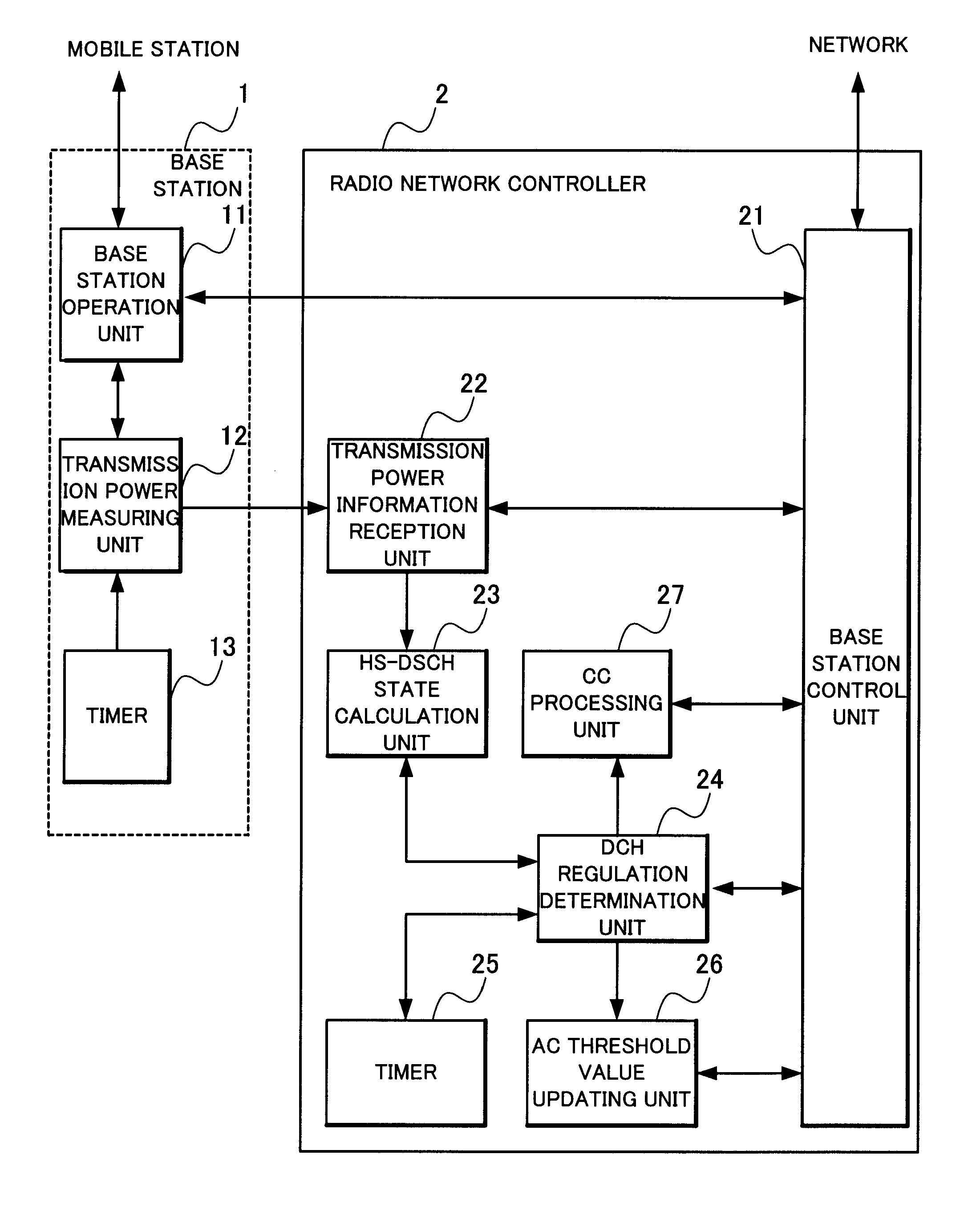
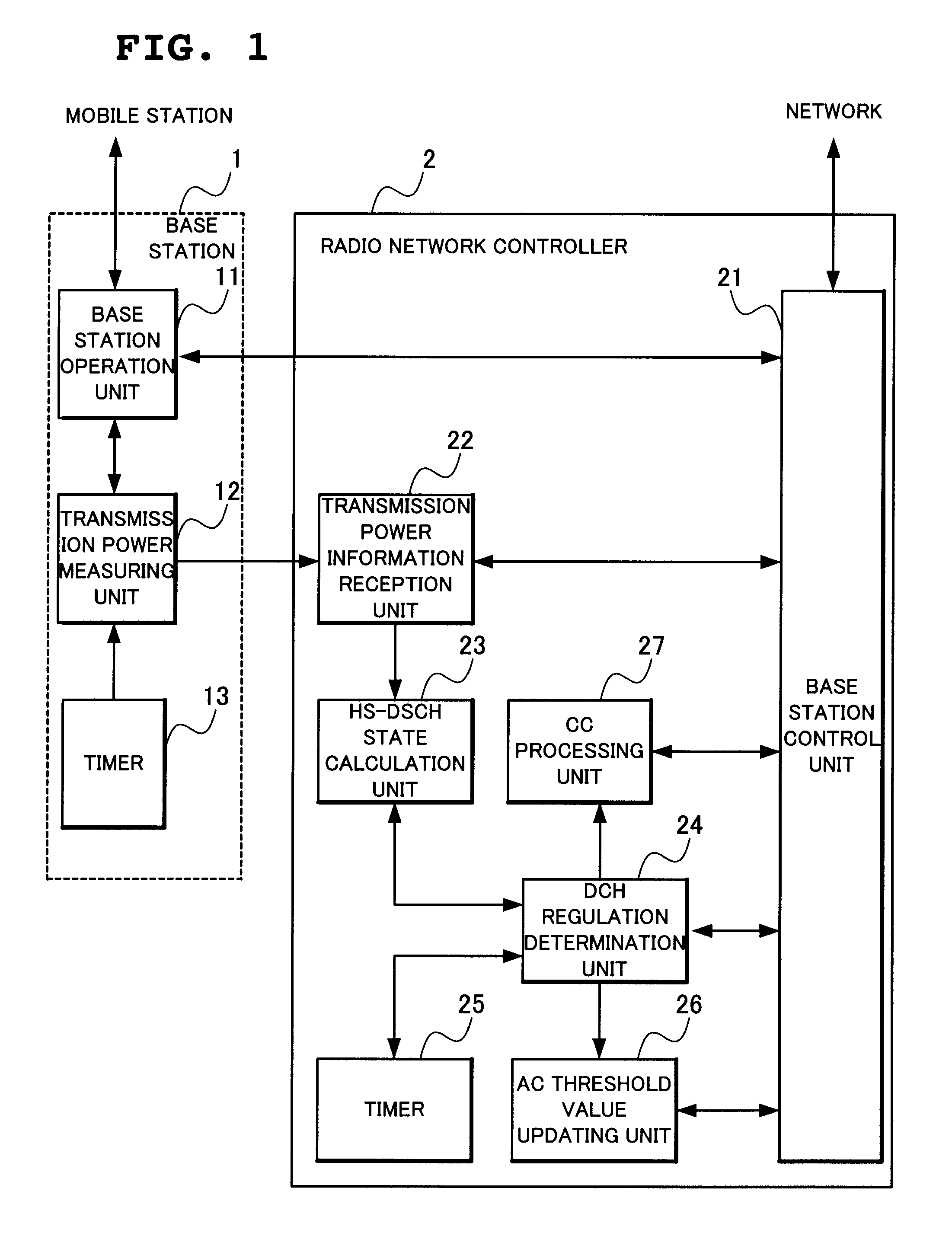
[0087]Next, a first embodiment of the present invention will be described. FIG. 1 is a block diagram showing one example of a basic structure of a base station and a radio network controller in the embodiment of the present invention.

[0088]With reference to FIG. 1, a base station 1 includes a base station operation unit 11 connected to a plurality of mobile stations not shown, a transmission power measuring unit 12 and a timer 13. A radio network controller 2 includes a base station control unit 21 connected to a network not shown, a transmission power information reception unit 22, an HS-DSCH state calculation unit 23, a DCH regulation determination unit 24, a timer 25, an AC threshold value updating unit 26 and a CC processing unit 27.

[0089]HS-DSCH (High Speed-Downlink Shared Channel) is a transport channel name, which corresponds to HS-PDSCH as a physical channel. Similarly, DCH (Dedicated Channel) is a transport channel name, which corresponds to DPCH as a physical channel.

[0090...

second embodiment

[0125]Next, a second embodiment of the present invention will be described. Structure of the present embodiment is the same as that of the first embodiment shown in FIG. 1.

Description of Operation

[0126]Next, operation of the present embodiment will be descried with reference to the drawings.

[0127]The second embodiment differs from the first embodiment in changing the sequence chart of FIG. 6 to FIG. 7. With reference to FIG. 7, operation of the second embodiment of the present invention differs from that of the first embodiment in changing the steps at B4 and B5 in FIG. 6 to B11 and B12, respectively. More specifically, when there exists a mobile station having set up DCH of the IA class at B3, determine whether there exists a mobile station subscribing only to the IA class (S11) and when there exists a mobile station subscribing only to the IA class, make the base station control unit 21 select mobile stations to a maximum number of NRelease from among relevant mobile stations to r...

third embodiment

[0129]Next, a third embodiment of the present invention will be described. Structure of the present embodiment is the same as that of the first embodiment shown in FIG. 1.

Description of Operation

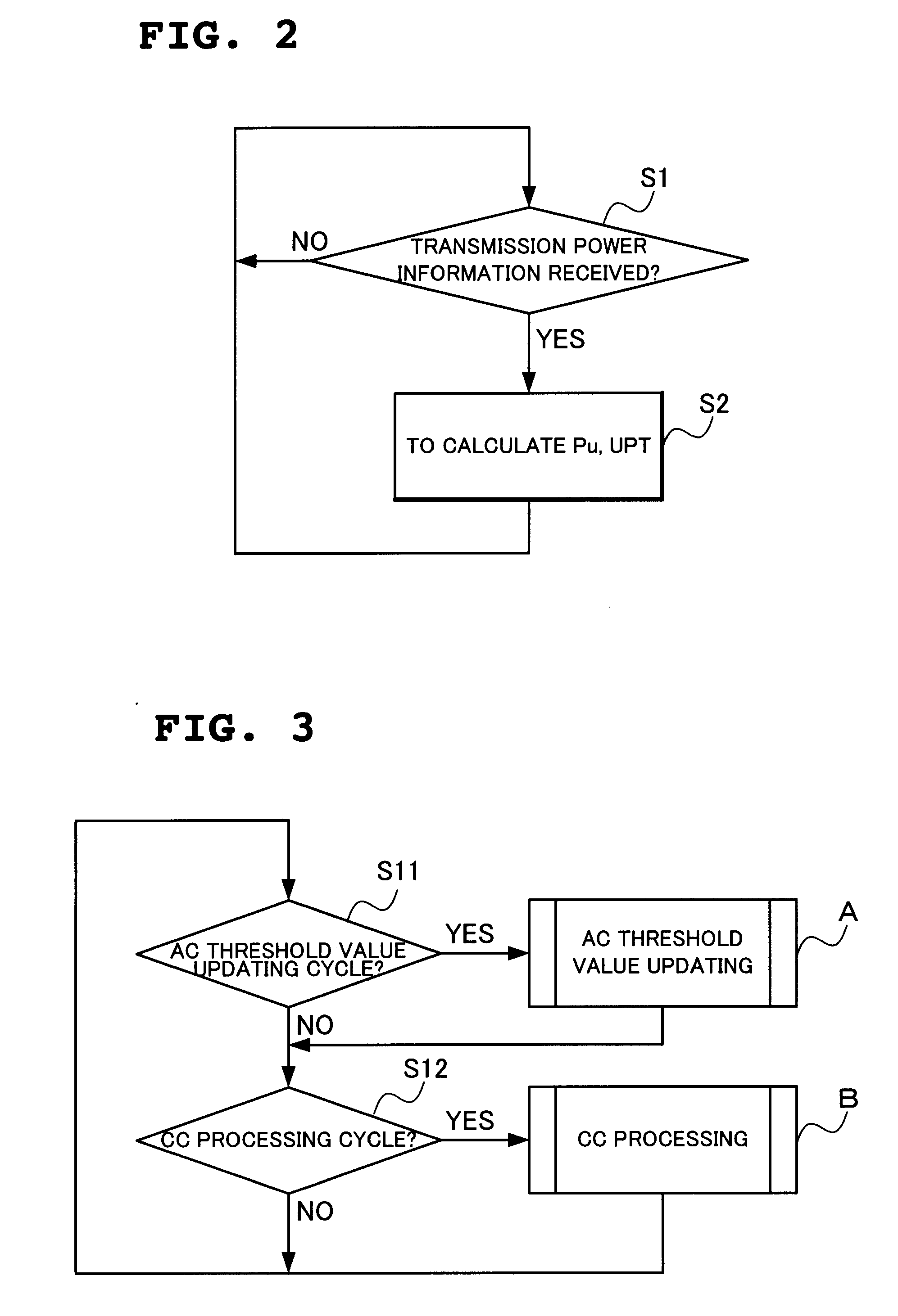
[0130]Operation of the present embodiment will be described with reference to the drawings. The third embodiment differs from the first embodiment in changing the sequence charts of FIG. 3 to FIG. 4 to those shown in FIG. 8 and FIG. 9.

[0131]With reference to FIG. 8, the present embodiment differs from the first embodiment in adding the steps of S21 and S22 prior to S11 in FIG. 3. More specifically, based on time-count information from the timer 25, the DCH regulation determination unit 24 determines whether the timer TimerAU_Update of the admission control threshold value updating cycle of DCH goes beyond an updating cycle TIAC_Update or not or whether a timer TimerCC of the congestion control executing updating cycle goes beyond an updating cycle TICC (S21). Upon determining that the TimerA...


PUM


Abstract

When determination is made that a channel for high-speed downlink packet transmission is short in power by the calculation of power assigned to a downlink shared channel and an activity ratio of the power assigned to the downlink shared channel from transmission power of all the channels and transmission power of other channel than a downlink shared channel for high-speed downlink packet transmission, a total sum of transmission power of dedicated channels is reduced by lowering a rate of a connected dedicated channel for data reception, thereby increasing power assigned to the channel for high-speed downlink packet transmission.

Description

FIELD OF THE INVENTION[0001]The present invention relates to a radio network controlling method, a radio communication system and a radio network controller and, more particularly, to a radio network controlling method in a system which executes high-speed downlink packet transmission, a radio communication system, and a radio network controller.DESCRIPTION OF THE RELATED ART[0002]As a system of transmitting data from a radio network controller in a mobile communication system to a mobile station in a cell under the control of a base station under the control of the radio network controller, defined in the specification (3GPP TS25.211 V5.5.0 (2003-09), 3GPP TS25.858 V5.0.0 (2002-03)) of the third generation mobile communication system standardization project 3GPP (3rd Group Partnership Project) and the like are a system using a downlink dedicated channel (DPCH: Dedicated Physical Channel) and the HSDPA system.[0003]DPCH is a dedicated channel set for each mobile station. On the othe...

Claims


Application Information

Patent Timeline
Patent Type & Authority Applications(United States)
IPC IPC(8): H04W74/00H04W28/22H04W52/04H04W52/16H04W52/26H04W52/32H04W52/34H04W72/54
CPCH04L1/0002H04L1/0021H04W28/22H04W52/143H04W52/346H04W52/267H04W52/325H04W52/343H04W52/16
Inventor NOBUKIYO, TAKAHIROHAMABE, KOJIRO
Owner NEC CORP
Why Eureka
Eureka Blog
Learn More