
Illuminated background system for aquarium

Inactive Publication Date: 2009-06-11
ALEMAN THOMAS
View PDF27 Cites 14 Cited by
  • Summary
  • Abstract
  • Description
  • Claims
  • Application Information

AI Technical Summary

Benefits of technology

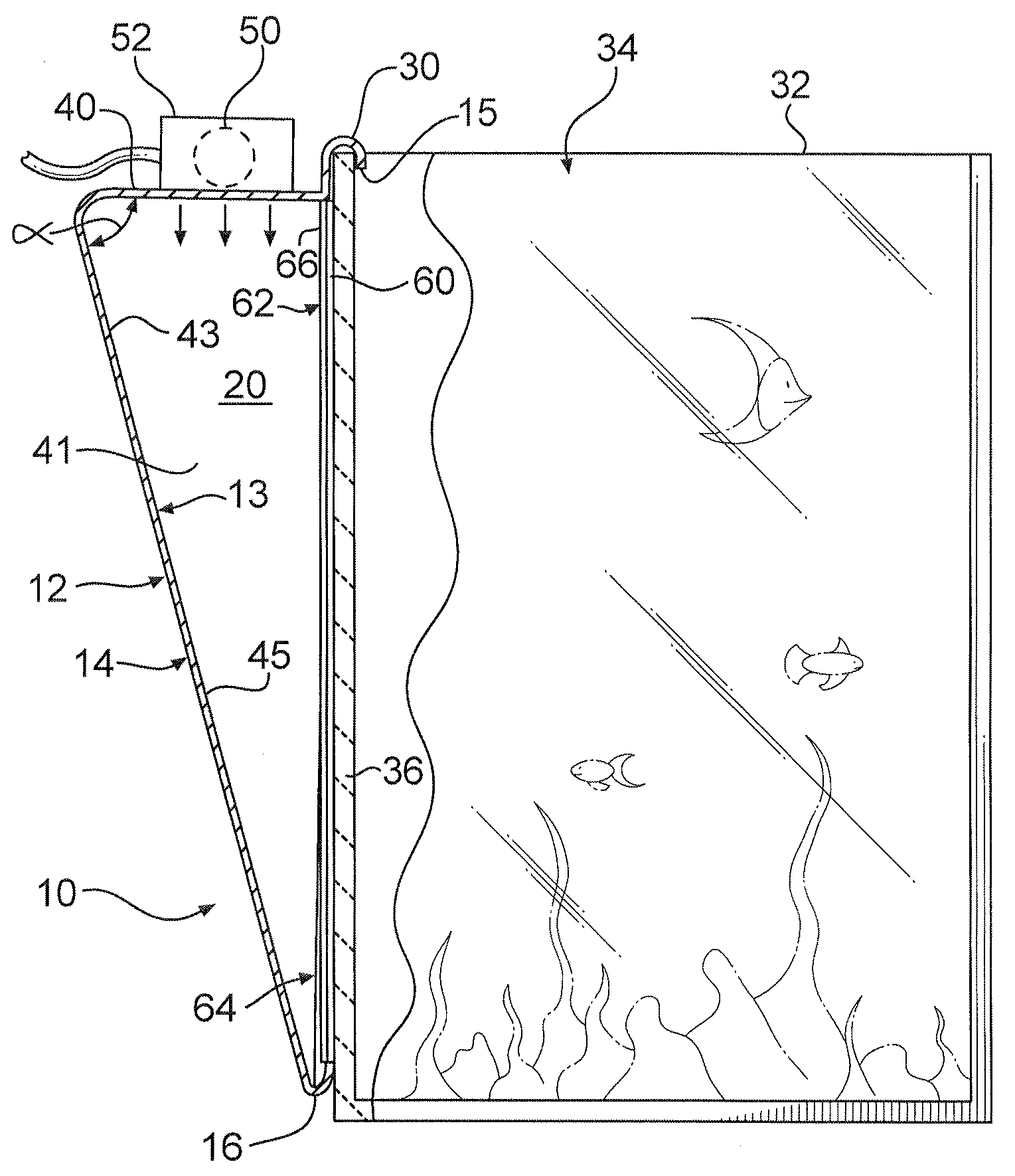
[0003]The present invention is therefore directed to an apparatus for illuminating a decorative scene disposed adjacent to or in proximity to a wall of an aquarium, terrarium, or other such enclosure. The invention provides an easy to use apparatus that effectively and uniformly illuminates a decorative background, which is selectively positioned within a mounting system associated with the illuminating system. The system is suitable for use with a wide variety of shapes and sizes of these types of enclosures. The invention is also cost effective to produce and use.
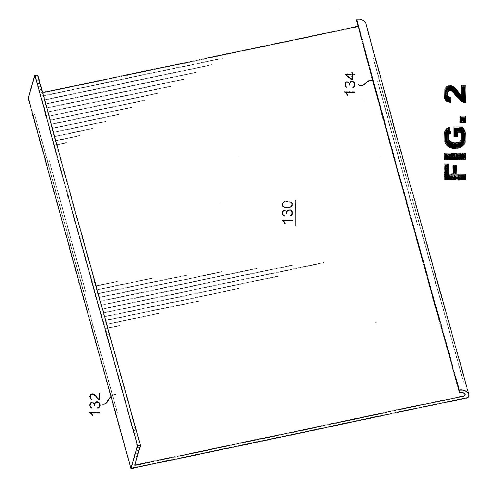
[0006]If desired, the housing may be adjustable in size to allow the apparatus to be utilized in conjunction with a variety of sizes of aquaria, terraria, or other such enclosures. This adjustability may be accomplished by forming housing from two or more separate members designed to be slidably connected. The members may be formed such that they slidably allow for the adjustment of the height of the apparatus, or adjustment of the lengthwise dimensions of the housing. The system may be formed of flat blanks which are easily folded and constructed to form the reflective enclosure, while allowing simplified and cost-effective manufacture and shipping.
[0007]Based upon the foregoing, the invention will provide an apparatus that is selectively attached to an aquarium, terrarium, or the like. If desired, the invention will provide uniform illumination through a wall of the enclosure to illuminate an entire decorative background provided in association with the wall of the enclosure, thereby dramatically improving the aesthetic appearance of the aquarium or the like.

Problems solved by technology

Although somewhat effective, these arrangements do not provide the correct source of light to effectively illuminate a decorative background.
Further, these sources of light would usually not provide sufficient light throughout the day to effectively illuminate the background.
Obviously, a window would generally only allow light in during “daylight” hours.
An ordinary lamp would also be ineffective because it provides an unevenly distributed source of light, and thus any extraneous illumination is generally ineffective.

Method used


Image

  • Illuminated background system for aquarium
  • Illuminated background system for aquarium
  • Illuminated background system for aquarium

Examples


Embodiment Construction

[0021]Detailed reference will now be made to several examples of the invention in the accompanying drawings.

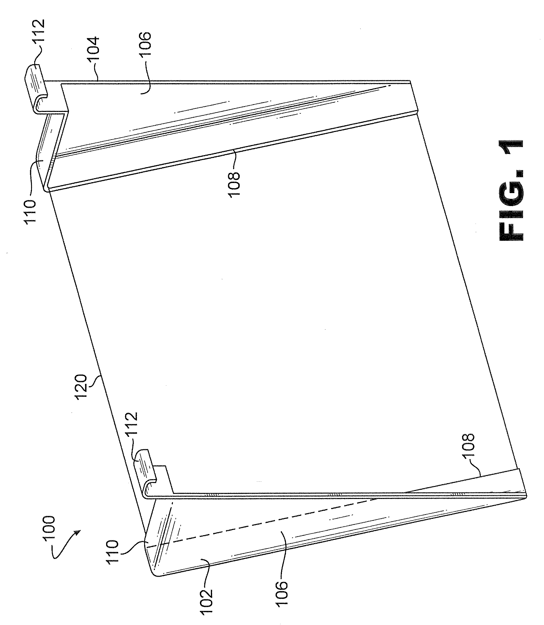
[0022]The invention in a first example as seen generally at 100 in FIG. 1, may comprise first and second housing members 102 and 104, formed as left and right hand members respectively, having triangular or other shaped side walls 106 and first and second flanges 108 and 110, extending away from the side wall along two sides. In one example, the housing members 102 and 104 may be formed to have approximately the cross-sectional shape of a right triangle such that the right angle is formed where the top wall of the housing member 102 and 104 meets the top region of a wall of the enclosure to which the apparatus is attached. The side wall 106 of each housing member may be dimensioned to correspond to the height of an enclosure with which it is to be used. The flanges 108 and 110 extend inwardly from the side wall on each of the right and left hand members 102 and 104, or toward ...


PUM


Abstract

The present invention relates generally to an illuminating apparatus and more particularly to an apparatus designed to backlight a decorative scene that may be adhered or otherwise disposed adjacent to a wall of an aquarium, terrarium, or similar enclosure. The apparatus may also be used to effectively illuminate the interior of an enclosure such as an aquarium or terrarium through a transparent side wall thereof.

Description

FIELD OF INVENTION[0001]The present invention relates generally to a simply produced and used illuminating apparatus and more particularly to an apparatus designed to backlight a decorative scene that may be provided in association therewith or disposed adjacent to a wall of an aquarium, terrarium, or similar enclosure. The apparatus may also be used to effectively illuminate the interior of an enclosure such as an aquarium or terrarium through a transparent side wall thereof.BACKGROUND[0002]Aquariums, terrariums, and other enclosures designed with transparent walls to allow the interior to be viewed are normally lighted, if at all, from a light source located in the lid or cover of the enclosure. To make the appearance of the enclosure more aesthetically pleasing, these types of enclosures may include decorative backgrounds such as a thin sheet of plastic having a decorative scene thereon adhered to or otherwise disposed adjacent to the back wall or side walls thereof. Light from t...

Claims


Application Information

Patent Timeline
IPC IPC(8): F21V33/00F21V7/00A01K63/06A47F11/10
CPCA01K63/006A47F3/001A01K63/06
Inventor ALEMAN, THOMAS
Owner ALEMAN THOMAS
Learn More