Load compensating hydraulic rate control

a hydraulic rate control and load compensation technology, applied in the field of rate controls, can solve the problems of increasing the size and weight of the rate control device, and the inability to control the fluid flow rate through the valve to a near constant rate over a wide range of applied loads

Active Publication Date: 2009-06-11
ITT ENIDINE
View PDF8 Cites 18 Cited by
  • Summary
  • Abstract
  • Description
  • Claims
  • Application Information

AI Technical Summary

Benefits of technology

[0008]It is an object of an aspect of the invention to provide a load compensating hydraulic rate control device.
[0009]It is an object of an aspect of the invention to provide a compact hydraulic rate control device exhibiting a relatively constant velocity of piston travel over a range of applied loads.
[0010]It is an object of an aspect of the invention to provide a hydraulic rate control device including a flow rate control valve having a self-adjusting valve member for controlling the flow rate of fluid through the piston head of the rate control device.
[0011]In an embodiment of the invention, a linear rate control device includes an outer cylinder defining an interior chamber having a longitudinal axis and containing a hydraulic fluid. A piston includes an axially slidable piston rod having a proximal end and a distal end and a piston head mounted to its proximal end and disposed within the interior chamber. The piston rod extends longitudinally along the longitudinal axis, of the interior chamber from the proximal end through a first end of the outer cylinder to the distal end thereof. A rate control valve is disposed within the piston head coaxially with the longitudinal axis of the cylinder within an interior cavity defined within the piston head. The rate control valve in conjunction with at least one hole in the piston head, defines a variable flow rate orifice and a fixed flow rate orifice disposed in series relationship with respect to fluid flow through the piston head and rate control valve. In an embodiment, the variable flow rate orifice forms a flow entrance for fluid flow to enter the rate control valve from the interior chamber of the cylinder on a high pressure side of the piston head and the fixed flow area orifice forms a flow exit for fluid flow to pass from the rate control valve into the interior chamber of the cylinder on a low pressure side of the piston head. In an alternate embodiment, the variable flow rate orifice forms a flow exit for fluid flow to pass from the rate control valve into the interior chamber of the cylinder on a low pressure side of the piston head and the fixed flow area orifice forms a flow entrance for fluid flow to enter the rate control valve from the interior chamber on a high pressure side of the piston head. In an embodiment, the linear rate control device includes a controlled flow passage established through the rate control valve during a movement of the piston rod under an applied compression load and an uncontrolled flow passage established outside the piston head during a movement of the piston rod under an applied tensile load. In an embodiment, the linear rate control device includes a controlled flow passage established through the rate control valve during a movement of the piston rod under an applied tensile load and an uncontrolled flow passage established outside the piston head during a movement of the piston rod under an applied compression load.
[0012]In an embodiment of the invention, a rate control device is provided having a substantially constant velocity characteristic over an applied load range. The rate control device includes an outer cylinder defining an interior chamber having a longitudinal axis and containing a hydraulic fluid. A piston includes a slidable piston rod having a proximal end and a distal end and a piston head mounted to its proximal end and disposed within the interior chamber. The piston rod extends longitudinally along the longitudinal axis of the interior chamber from the proximal end through a first end of the outer cylinder to the distal end thereof. A rate control valve is disposed within the piston head coaxially with the longitudinal axis of the cylinder and slidably retained within an interior cavity defined within the piston head. The rate control valve defines a subchamber within the interior cavity of the piston head. A bias spring is disposed within the interior cavity of the piston head in operative association with the rate control valve. The rate control valve includes a fixed flow area orifice, at least one hole radially through the rate control valve in communication with a groove on the outside of the rate control valve, whose groove edge, in combination with at least one first opening through the piston head, defines a variable flow area orifice. The fixed area orifice establishes a restricted fluid flow path between the subchamber within the rate control valve and the interior chamber of the cylinder on one of a low pressure side of the piston head or a high pressure side of the piston head. The variable flow area orifice establishes a restricted fluid flow path between the subchamber within the rate control valve and the interior chamber on the other one of the high pressure side of the piston head or the low pressure side of the piston head. The variable flow area orifice is formed cooperatively by registration of a groove edge on the rate control valve and at least one first opening through the piston head. The rate control valve is axially repositionable within the interior cavity of the piston head against the bias spring in response to the fluid pressure within the subchamber of the rate control valve to vary the flow area through the variable flow area orifice.
[0013]In an embodiment of the invention, a rate control device is provided having a substantially constant velocity characteristic over a range of applied load for both compression and tension loading. The rate control device includes an outer cylinder defining an interior chamber having a longitudinal axis and containing a hydraulic fluid. A piston includes a slidable piston rod having a proximal end and a distal end and a piston head mounted to its proximal end and disposed within the interior chamber. The piston rod extends longitudinally along the longitudinal axis of the interior chamber from the proximal end through a first end of the outer cylinder to the distal end thereof. A rate control valve is slidably retained within an interior cavity defined within the piston head and disposed coaxially with the longitudinal axis of the cylinder. In this embodiment, the rate control valve defines an interior chamber and having an interior wall dividing the interior chamber of the valve into a first subchamber and a second subchamber. A first bias spring is disposed in the interior cavity of the piston head in operative association with and forwardly of the rate control valve. A second bias spring is disposed in the interior cavity of the piston head in operative association with and rearwardly of the rate control valve. A fixed flow area orifice is provided in the interior wall of said rate control valve to establish a restricted internal fluid flow path between the first and second subchambers. In this embodiment, a groove on the outside of the rate control valve, whose groove edge, in combination with at least one first opening through the piston head, defines a first variable flow area orifice that establishes a restricted fluid flow path between the first subchamber and the interior chamber of the cylinder on one of a high pressure side of the piston head or a low pressure side of the piston head and a second variable flow area orifice that establishes a restricted fluid flow path between the second subchamber and the interior chamber on the other of a low pressure side of the piston head or a high pressure side of the piston head. The rate control valve is axially repositionable within the interior cavity of the piston head against one of the first and second bias springs in response to an intermediate fluid pressure within one of the first and second subchambers to vary the flow area through one of the first and second variable flow area orifices. This embodiment provides either equal constant velocity control in both directions or different constant velocity control in each direction.

Problems solved by technology

However, since the spring biasing the tapered pin within the orifice opening in the face of the valve must have a high enough spring rate to work effectively at the higher applied loads, control of fluid flow rate through the valve to a near constant rate is not achievable over a wide range of applied loads.
However, given the radially outward positioning of the flow control valves, a relatively large diameter cylindrical housing is required which increases both the size and weight of this rate control device.

Method used


Image

  • Load compensating hydraulic rate control
  • Load compensating hydraulic rate control
  • Load compensating hydraulic rate control

Examples


Embodiment Construction

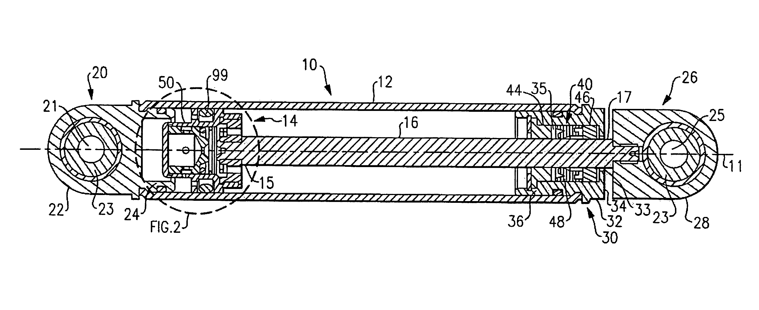
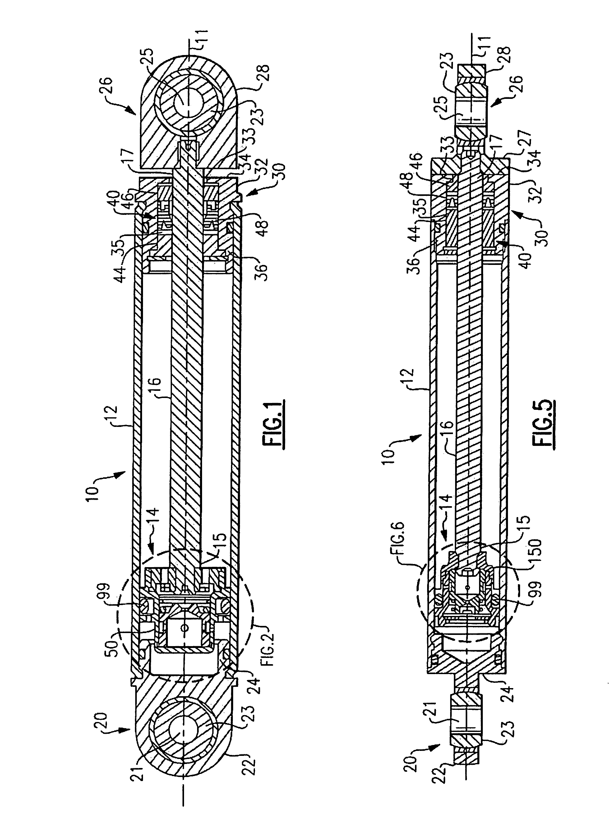
[0026]Referring initially to FIGS. 1 and 5 of the drawing, there are depicted exemplary embodiments of a hydraulic rate control device 10 in accordance with the present invention. The rate control device 10 includes a cylindrical tube 12 extending along a longitudinal axis 11 and a piston assembly 14 that includes a piston rod 16 having a proximal end 15 and a distal end 17, and a piston head assembly 50, 150 mounted to the proximal end 15 of the piston rod 16 and housed within the interior of the cylindrical tube 12. The cylindrical tube 12 has a first cylinder end assembly 20 mounted to a first end of the cylindrical tube 12 and a second cylinder end assembly 30 mounted to a second end of the cylindrical tube 12. The first cylinder end assembly 20 includes an end member 22 defining an eye socket 21 housing a spherical bearing 23 and having a base end 24 extending into the first end of the cylindrical tube 12 in scaled relationship with the inner wall of the cylindrical tube 12. Th...


PUM


Abstract

A rate control device includes an outer cylinder defining an interior chamber having a longitudinal axis and containing a hydraulic fluid. A piston head mounted to a proximal end or a piston rod is slidably positionable within the interior chamber. A rate control valve is disposed within an interior cavity of the piston head coaxially with the longitudinal axis of the interior chamber of the cylinder. The rate control valve includes a variable flow rate orifice and a fixed flow rate orifice disposed in series relationship with respect to fluid flow through the rate control valve.

Description

FIELD OF THE INVENTION[0001]This invention relates generally to rate controls for use in connection with a hydraulic piston-type device and, more particularly, to a hydraulic linear rate control device providing a near constant piston rod velocity over a wide range of applied loads.BACKGROUND OF THE INVENTION[0002]Hydraulic rate control piston-type devices are used in a wide variety of applications to support a component from a structural member and control the pivotal movement of the component. For example, hydraulic rate control piston-type devices arc commonly used oil commercial passenger aircraft to support and control the opening rate of pivoting type overhead stowage bins. U.S. Pat. No. 6,874,731 discloses a modular overhead stowage bin system for an aircraft passenger cabin. In a wide body, multi-aisle aircraft, the overhead stowage bins include outboard stowage bins positioned above the right and left side seats of the aircraft and inboard stowage bins positioned above the ...

Claims


Application Information

Patent Timeline
Patent Type & Authority Applications(United States)
IPC IPC(8): F16F5/00F16F9/32
CPCF16F9/5126F16F9/3405G05D7/0133Y10T137/2202
Inventor BOERSCHIG, TIMOTHY J.
Owner ITT ENIDINE
Why Eureka
Try Eureka