Solar-panel unit

Inactive Publication Date: 2009-06-11
LASEN DEV
View PDF42 Cites 19 Cited by
  • Summary
  • Abstract
  • Description
  • Claims
  • Application Information

AI Technical Summary

Benefits of technology

[0004]The aim of the present invention is to provide a solar-panel unit that will enable a simple solution at contained costs of the problems set forth above.

Problems solved by technology

Albeit used, the known solar-panel units of the type described above prove to be not altogether satisfactory as regards efficiency, in so far as the presence of a single panel and the adjustment about a vertical axis do not enable optimal exposure to solar radiation to be obtained, above all owing to the fact that different areas of the panel at different times of the day are in partial or total shade, thus reducing the efficiency of the unit proportionally.

Method used


Image

  • Solar-panel unit
  • Solar-panel unit
  • Solar-panel unit

Examples


Embodiment Construction

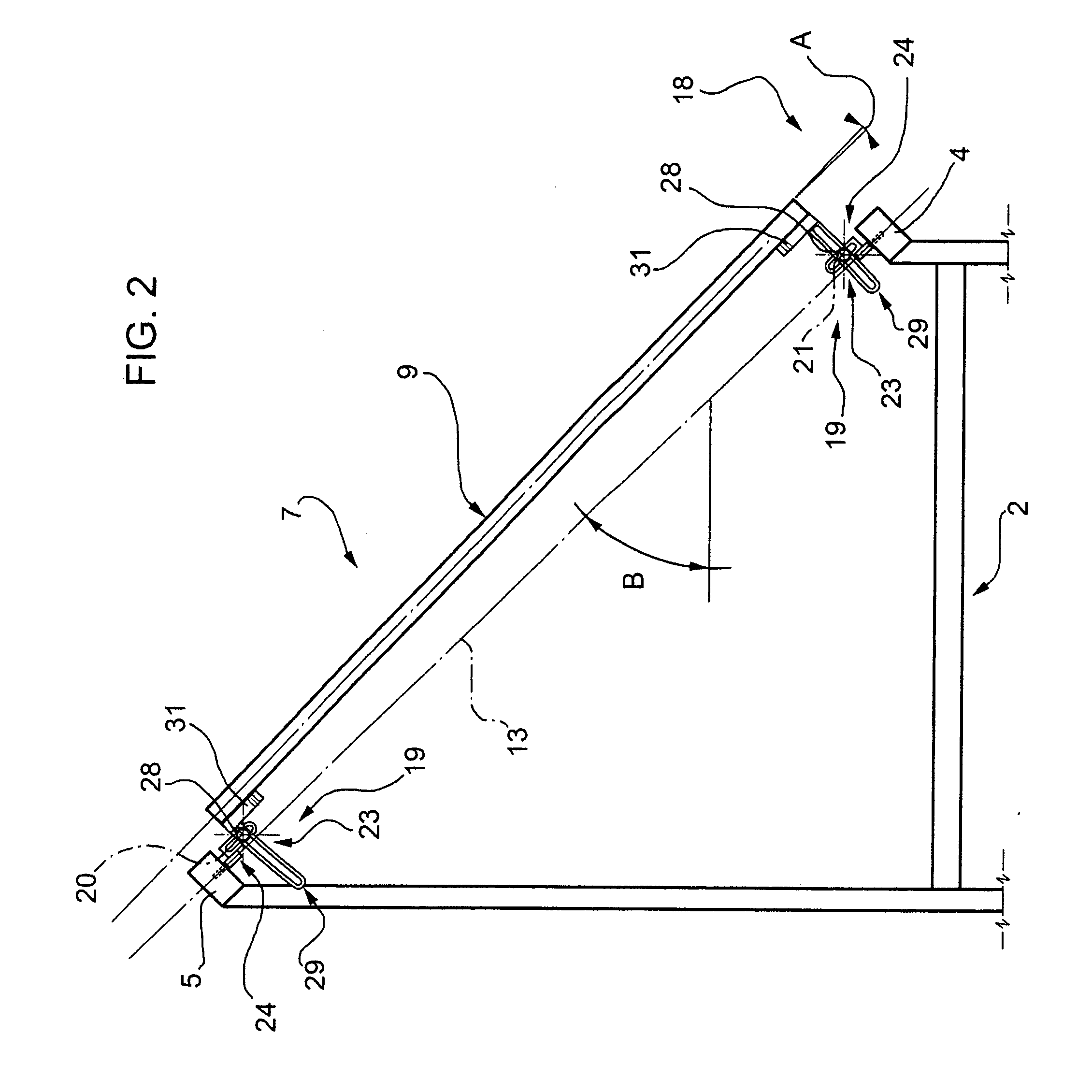
[0012]In FIG. 1, designated as a whole by 1, is a solar-panel unit comprising a supporting structure 2, which is designed to be fixed to a fixed support 3 and in turn comprises a bottom cross member 4 and a top cross member 5, which is set parallel and in raised position with respect to the bottom cross member 4 itself.

[0013]Once again with reference to FIG. 1, the unit 1 moreover comprises a plurality of inclined solar panels 7 extending in positions set alongside one another between the cross members 4 and 5 and orthogonal to the cross members 4 and 5 themselves. Each solar panel 7 conveniently has an elongated rectangular shape, is delimited by an extensive plane surface 9 of incidence of the solar radiation, and is, preferably but not necessarily, of a photovoltaic-cell type.

[0014]Each panel 7 comprises respective opposite end portions 10, hinged to the cross members 4 and 5 via respective hinge-pins 11 for turning in opposite directions about a fixed inclined fulcrum or hinge a...


PUM


Abstract

A solar-panel unit is provided with: an attachment structure; at least one solar panel, which is delimited by an extensive plane surface of incidence of the solar radiation and is connected to the attachment structure; and a hinging assembly, set between the attachment structure and the solar panel, to enable rotation of the solar panel with respect to the attachment structure about an inclined hinge axis forming an angle smaller than 90° with a horizontal plane.

Description

[0001]The present invention relates to a photovoltaic-panel unit.BACKGROUND OF THE INVENTION[0002]In the field of use of solar energy, it is known to use solar-panel units, each of which comprises a supporting structure designed to be anchored to the ground, and a plate-type solar panel. In some applications, the plate-type solar panel is stably connected to the supporting structure, whilst in other cases the supporting structure is hinged to a fixed support for turning whit the panel about a vertical axis.[0003]Albeit used, the known solar-panel units of the type described above prove to be not altogether satisfactory as regards efficiency, in so far as the presence of a single panel and the adjustment about a vertical axis do not enable optimal exposure to solar radiation to be obtained, above all owing to the fact that different areas of the panel at different times of the day are in partial or total shade, thus reducing the efficiency of the unit proportionally.SUMMARY OF THE IN...

Claims


Application Information

Patent Timeline
IPC IPC(8): F24J2/48F24S23/00F24S23/71
CPCF24J2/5264F24J2/5413F24J2002/5451H02S20/00Y02E10/47Y02E10/50F24J2002/5468H02S20/30H02S40/44H02S40/425Y02E10/60F24S30/428F24S2030/131F24S25/70F24S2030/136
Inventor CARCANGIU, GIACOMOSARDO, MARCELLOCARCANGIU, IGNAZIOSARDO, ROCCO
Owner LASEN DEV
Why Eureka
Try Eureka