Orthotic apparatus and method for using same
a technology of orthopaedic devices and cuffs, applied in the field of orthopaedic devices, can solve the problems of difficult to apply, difficult to apply, and pain in the pressure on the limbs by the cuffs, and achieve the effects of easy application and removal, increased reliability, and high load application
- Summary
- Abstract
- Description
- Claims
- Application Information
AI Technical Summary
Benefits of technology
Problems solved by technology
Method used
Image
Examples
first embodiment
FIGS. 1-4
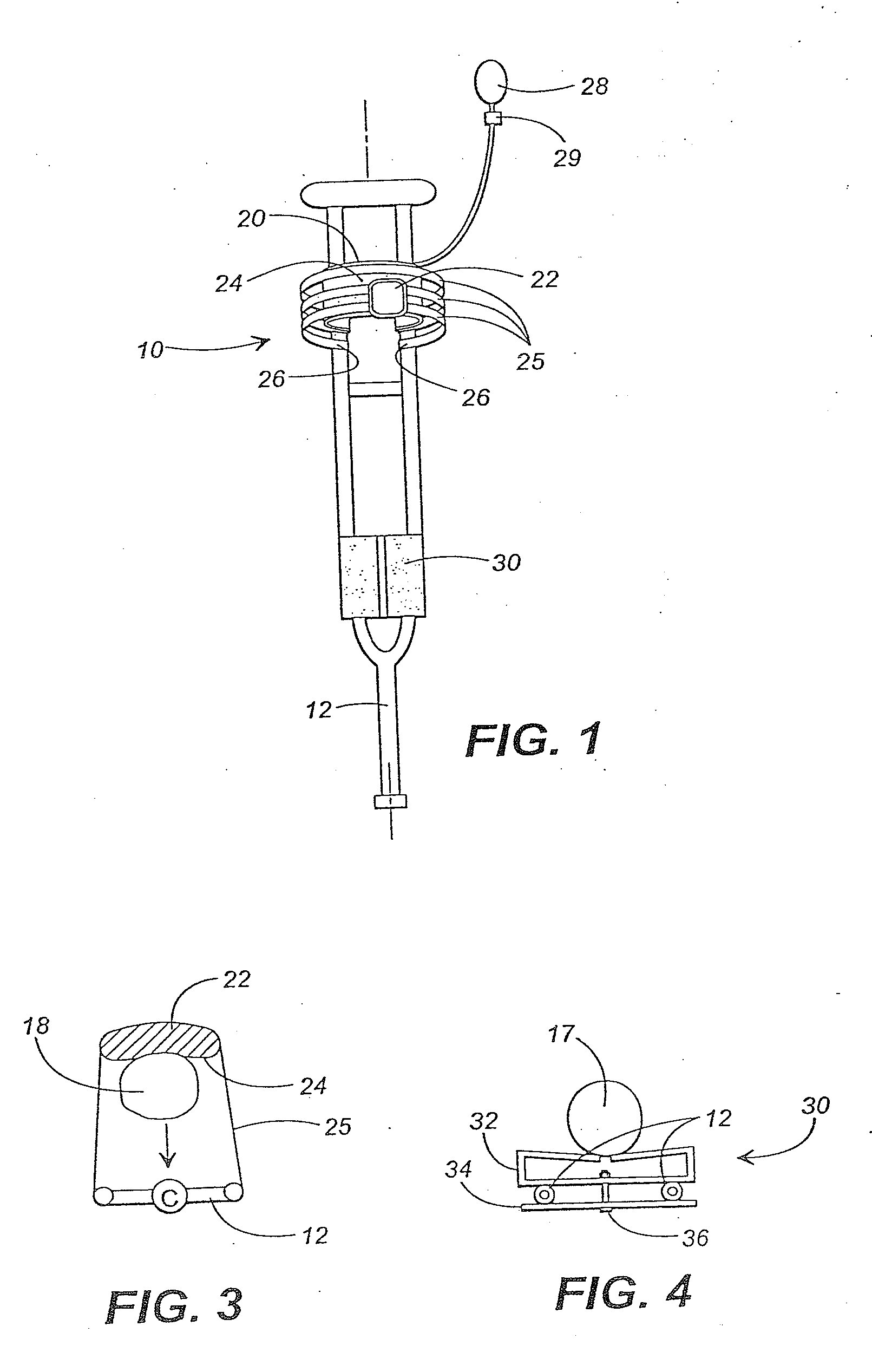
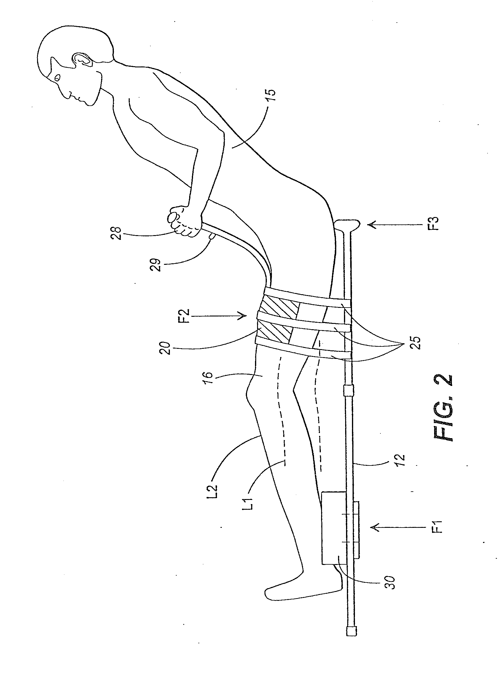
[0053]FIG. 1 is a front view of a knee extension assembly 10 and an ankle support member 30 used in conjunction with a conventional crutch 12. FIG. 2 is a is a side view of the elements 10, 12, 30 being used by a wearer 15. FIG. 3 is a top cross-sectional view taken transverse to the longitudinal axis of the crutch and the wearer's leg of FIG. 2, with the cross-section taken through the inflatable air bladder. FIG. 4 is another transverse cross-section taken from the FIG. 1 configuration, but this time the cross-section is taken just above the ankle support member 30.
[0054]The crutch as shown in FIG. 1 is a conventional type of crutch, which is a distinctive aspect of the present invention in that conventional crutches are readily available within the market. The present invention particularly adds the use of a knee extension assembly 10 and an ankle support member 30.
[0055]The knee extension assembly 10 includes an inflatable member 20, a plurality of straps 25, and a conv...
second embodiment
FIG. 5
[0063]FIG. 5 illustrates the use of a rigid plastic or other suitable material, to provide an elongate structural member 210 which may be attached to the underside of the arm, with its lower end extending beyond the elbow, terminating in a “free end”. Approximate this “free end” are attached three (as shown) straps 225 which connect an inflatable member 220 (an air bladder in a fabric pouch) to the free end of the elongate member. This member 220 is configured to be positioned adjacent to the forearm of a wearer, such that inflation of the air bag therein tends to provide pressure causing movement such as shown as M. This is conventionally called “extension” and is desired in certain types of orthotics.
[0064]It should be understood that this FIG. 5 configuration includes the “three point” force combination as described above. However, this FIG. 5 configuration is similar to the FIGS. 6 and 7 configuration, and the “three point” force configuration will be described in more det...
third embodiment
FIGS. 6 and 7
[0065]FIGS. 6 and 7 show a third embodiment of the present invention, being an apparatus 300 configured to be attached to the arm of a wearer 315. It should be understood that FIG. 6 is a more simplified version.
[0066]The apparatus 300 includes a substantially rigid structural frame 301 including a forearm bearing portion 302 and an upper arm bearing portion 304, connected by one or more connecting members 306. Also included are straps 325 and an inflatable member 320, which can include an inflatable bladder contained by a fabric pouch. As are other configurations discussed herein, the straps are sewn to the fabric pouch by conventional means. As elsewhere in this discussion VELCRO-type attachments at 327 may be provided for detachability and adjustability of the straps.
[0067]Flanges 305 (see FIG. 7) may be optionally used if desired to extend upwardly on either side of the main body to contain the forearm as desired.
[0068]FIG. 7 shows the embodiment in slightly more de...
PUM
 Abstract
Description
Claims
Application Information
 - R&D
- Intellectual Property
- Life Sciences
- Materials
- Tech Scout
- Unparalleled Data Quality
- Higher Quality Content
- 60% Fewer Hallucinations
Browse by: Latest US Patents, China's latest patents, Technical Efficacy Thesaurus, Application Domain, Technology Topic, Popular Technical Reports.
© 2025 PatSnap. All rights reserved.Legal|Privacy policy|Modern Slavery Act Transparency Statement|Sitemap|About US| Contact US: help@patsnap.com


