
Display System and Method

a display system and display technology, applied in the field of multi-display technology, can solve the problems of not being able to achieve the high throughput required by the display device, not having a mature solution for usb/pcie or uwb to support a second display device, and complicated notebook computers to support all types of interfaces. complexity, the effect of reducing the requirement for bandwidth

Active Publication Date: 2009-06-04
LENOVO (BEIJING) LTD
View PDF1 Cites 16 Cited by
  • Summary
  • Abstract
  • Description
  • Claims
  • Application Information

AI Technical Summary

Benefits of technology

[0024]With the above configuration of the present invention, requirement on bandwidth is lowered since only the dynamically changing part of the screen data in the video signals or the full-screen data is first compressed and then transmitted to the display device side via USB interface or in the form of UWB. In addition, the present invention can be realized with a low-cost embedded CPU, FPGA or application-specific chip, with a reduced complexity of the system.

Problems solved by technology

Accordingly, the notebook computer will become complicated and clumsy in order to support all types of these interfaces.
Unfortunately, there has not been any mature solution for USB / PCIe or UWB to support a second display device, that is, for the conversion from USB / UWB / PCIe to VGA / DVI / Displayport, etc.
In this way, the high throughput required by the display device cannot be well achieved due to the bandwidth of IEEE802.11, and thus it is necessary to employ a deeply lossy compression scheme.
This would result in the problem that the displayed image cannot resemble and synchronize with the original one very well, leading to the degrading of screen quality and color distortion.
Meanwhile, the above scheme burdens both of the computer and the display device with a heavy computational load, and thus affects the system performance to a great extent.
Moreover, cost tends to be uncontrollable, since the display side usually requires a typical embedded system including CPU / OS / DSP to retrieve the video and output.
In conclusion, because of the limited bandwidth of the existing 802.11 system, screen data of high-quality cannot be transmitted timely to the display device side while the computer is playing real-time video, especially video of high-quality.

Method used


Image

  • Display System and Method
  • Display System and Method
  • Display System and Method

Examples


first embodiment

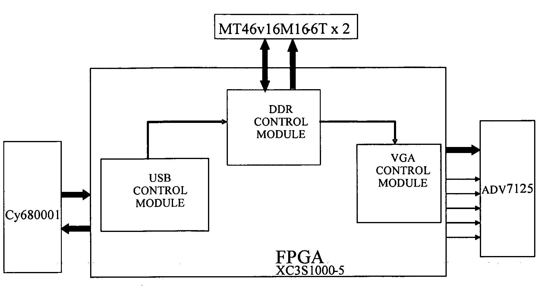
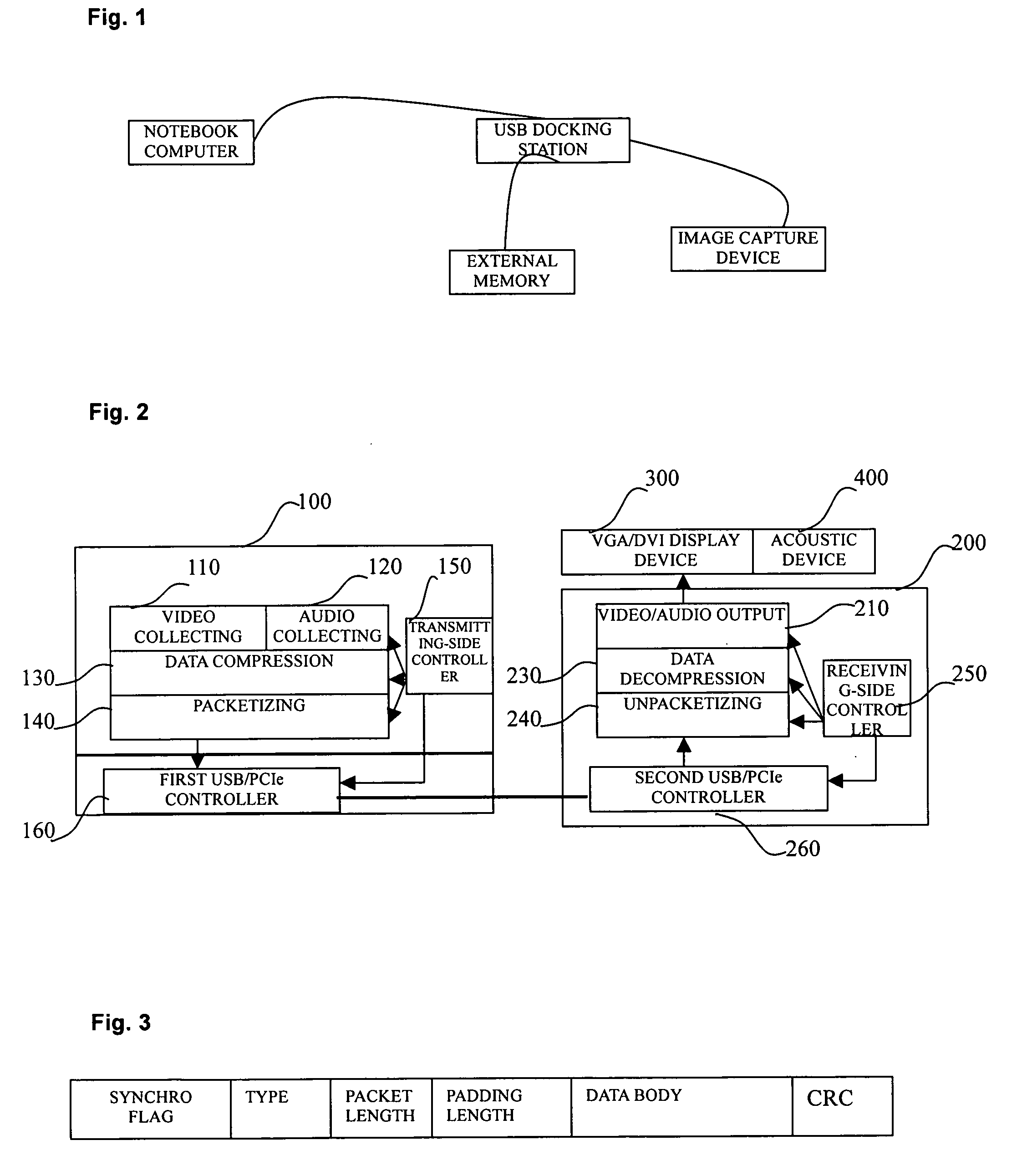
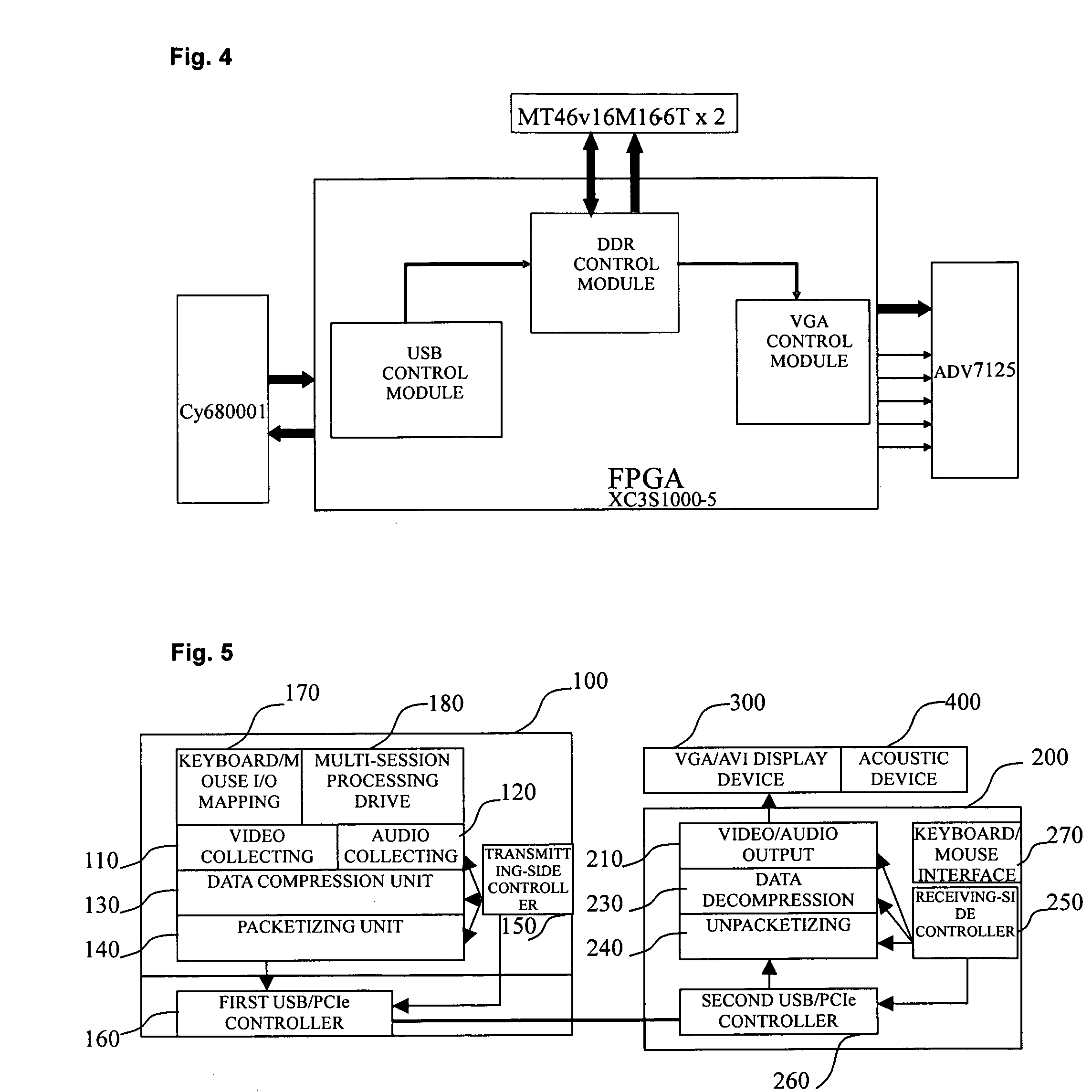
[0034]FIG. 2 shows a block diagram of a display system according to the present invention.

[0035]As shown in FIG. 2, the display system of the first embodiment comprises a data transmitting apparatus 100 built in a host, say, a notebook computer, a VGA / DVI display device 300 and an acoustic device 400 located remotely, and a data receiving apparatus 200 connected to the display device 300 and the acoustic device 400 and for receiving multimedia data from the host side and converting the data into a format supported by a VGA / PCI display device.

[0036]The data transmitting apparatus 100 includes a video collecting unit 110 which collects dynamically changing screen data or full-screen data in current video signals, from the host like a notebook computer, a audio collecting unit 120 which collects audio signals synchronously with the current video signals or separate audio signals from the host to obtain audio data, a data compression unit 130 which compresses the screen data and the aud...

second embodiment

[0051]FIG. 6 is a block diagram for a wireless display system according to the present invention.

[0052]As shown in FIG. 6, the data transmitting apparatus 100 built in the host comprises a data collecting unit 510, a packetizing unit 520, a first UWB (Ultra Wideband) transceiving unit 530 and a transmitting-side controller 540. The data receiving apparatus 200 connected to a display device and an acoustic device (not shown) comprises a second UWB transceiving unit 610, a receiving-side controller 620, a unpacketizing unit 630 and an output unit 640.

[0053]The host here can be all kinds of computer mainframes, such as the mainframe for a PC for a server, a notebook computer, a handheld device like a cell phone and PDA, etc.; the display device 300 can be various display devices, such as the monitor (LCD, CRT or the like) of a computer, a projector or a television.

[0054]In the data transmitting apparatus 100, the data collecting unit 510 acquires display data from the host OS. The pack...


PUM


Abstract

A display system and method are disclosed. The system comprises a data transmitting apparatus built in a computer and a data receiving apparatus connected to a remote VGA / DVI display device, in which the data transmitting apparatus comprises a collecting unit for collecting screen data and / or audio data in video signals and a local control unit for encoding said screen data and / or audio data and transmitting said encoded screen data and / or audio data; the data receiving apparatus comprises a remote control unit for controlling the reception of said screen data and / or audio data and decoding it, a buffer unit for controlling the audio / video data decoded by the remote control unit to be placed into a memory for buffering, and an output unit for converting the buffered screen data and / or audio data into a format supported by the VGA / DVI display device and / or audio format.

Description

BACKGROUND OF THE INVENTION[0001]1. Field of Invention[0002]The present application relates to multi-display technology, in particular to a display system and method capable of supporting multi-display.[0003]2. Description of Related Prior Art[0004]With the development of various interface techniques, the notebook as a portable computer is required to support a variety of peripheral interfaces such as USB, serial and parallel port, network interface, VGA / DVI / HDMI interface and Displayport interface in the future. Accordingly, the notebook computer will become complicated and clumsy in order to support all types of these interfaces.[0005]In view of the above issues, a concept has been proposed in the art that is based on the port replicator or docking station. That is, a peripheral device is designed as an attachment to the notebook computer and placed near the computer or under the base of the computer in a wired way, such as USB / PCIe, or in a wireless way, such as UWB. All kinds of...

Claims


Application Information

Patent Timeline
Patent Type & Authority Applications(United States)
IPC IPC(8): H04N5/66H04N7/12
CPCG06F3/14G09G2340/02G09G5/363
Inventor GUO, ZIHUAYAN, XIAOPINGWEI, WEI
Owner LENOVO (BEIJING) LTD
Learn More