
Wind energy system having an insect sensor

a technology of wind energy system and insect sensor, which is applied in the direction of wind energy generation, mechanical power/torque control, ratio control, etc., can solve the problems of reducing output, most inefficient waiting for rain, and so on

Inactive Publication Date: 2009-06-04
GENERAL ELECTRIC CO
View PDF12 Cites 15 Cited by
  • Summary
  • Abstract
  • Description
  • Claims
  • Application Information

AI Technical Summary

Benefits of technology

[0009]According to a further aspect, a computer-readable medium is provided that provides instructions which when executed by a computing platform cause the computing platform to perform operations wherein these operations comprise the method steps according to the method as described herein.

Problems solved by technology

In particular in summer with low winds after rain, insects such as bugs often fly into the rotor of a wind energy system and splatter on the leading edge of the wind energy system rotor blades thereby soiling lift and reducing output.
However, waiting for rain is most inefficient particularly at those wind energy systems sites being located in dry regions.
However, the blade washing equipment known in the art has several drawbacks.
First of all, the equipment of a wind energy system with blade washing equipment is a complex and expensive issue.

Method used


Image

  • Wind energy system having an insect sensor
  • Wind energy system having an insect sensor
  • Wind energy system having an insect sensor

Examples


Embodiment Construction

[0019]Reference will now be made in detail to the various embodiments of the invention, one or more examples of which are illustrated in the figures. Each example is provided by way of explanation of the invention, and is not meant as a limitation of the invention. For example, features illustrated or described as part of one embodiment can be used on or in conjunction with other embodiments to yield yet a further embodiment. It is intended that the present invention includes such modifications and variations.

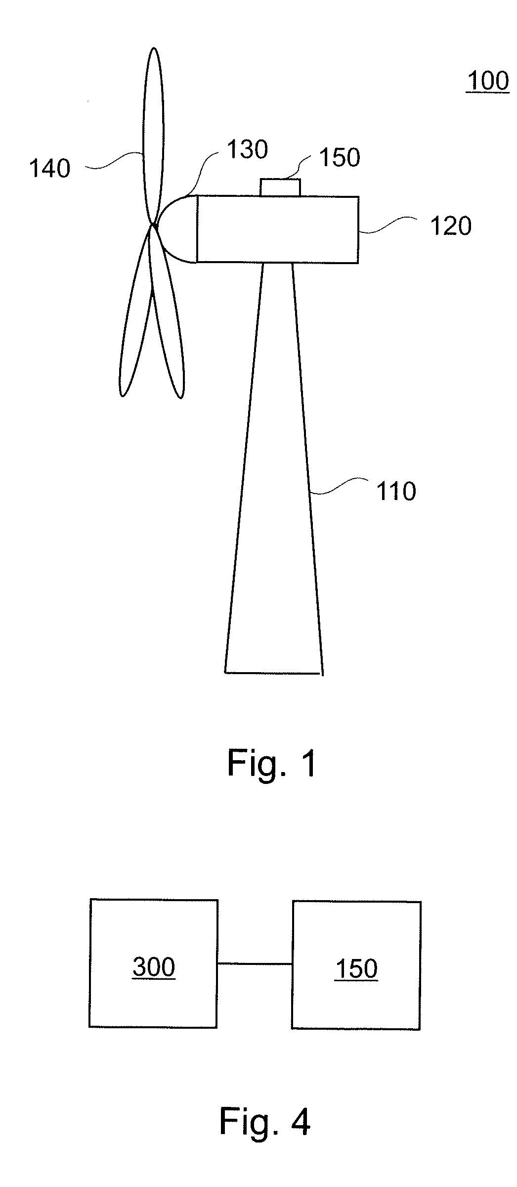
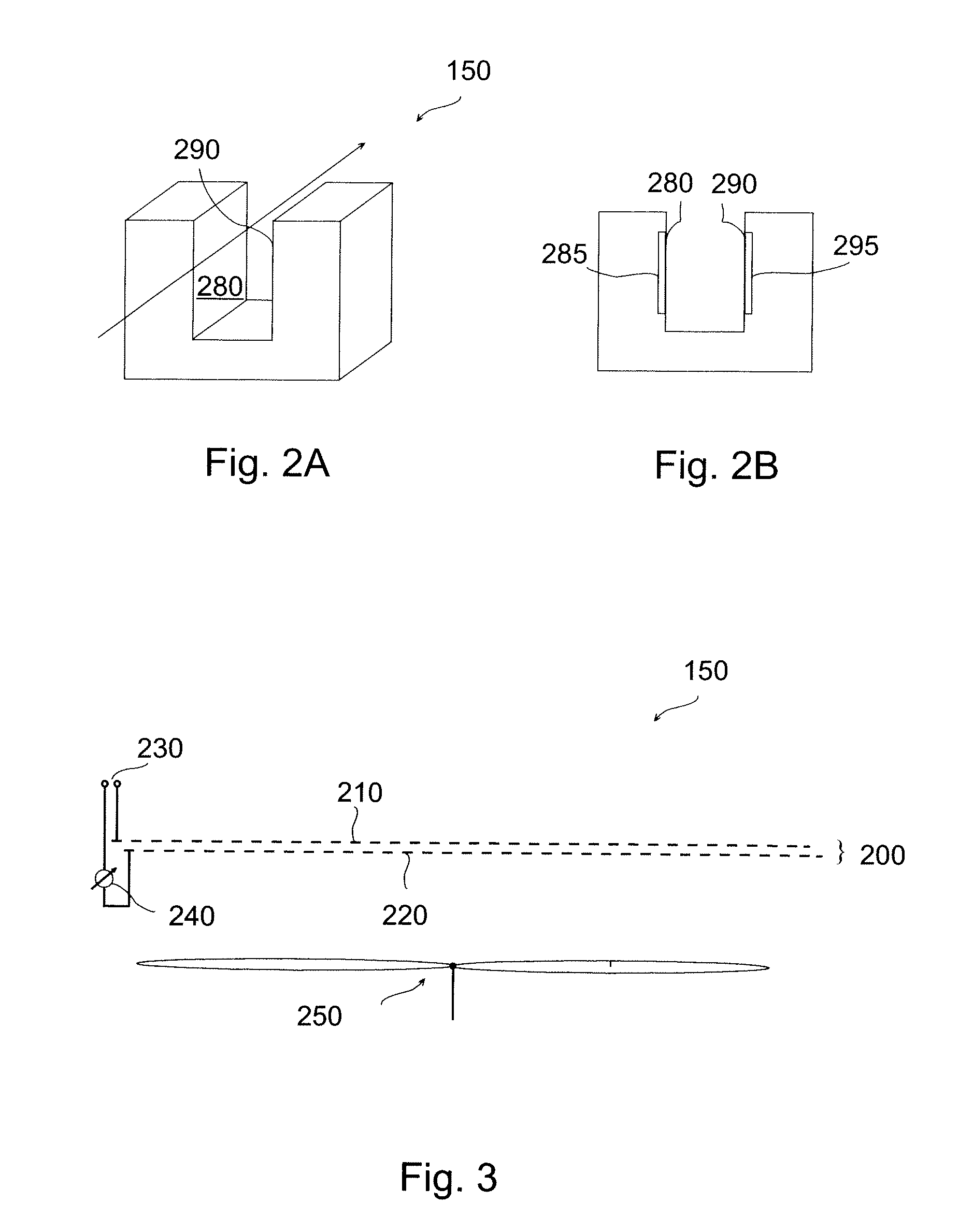
[0020]FIG. 1 is a schematic view of a wind energy system. The wind energy system 100 has a tower 110 to which a machine nacelle 120 is mounted at its top end. The nacelle houses a drive train to which an electric generator is connected (not shown). The hub 130 bearing three rotor blades 140 is mounted to a lateral end of the machine nacelle 120. The rotor blades 140 can be adjusted by pitch drives which are typically accommodated inside hub 130. FIG. 1 is for illustrative purpo...


PUM


Abstract

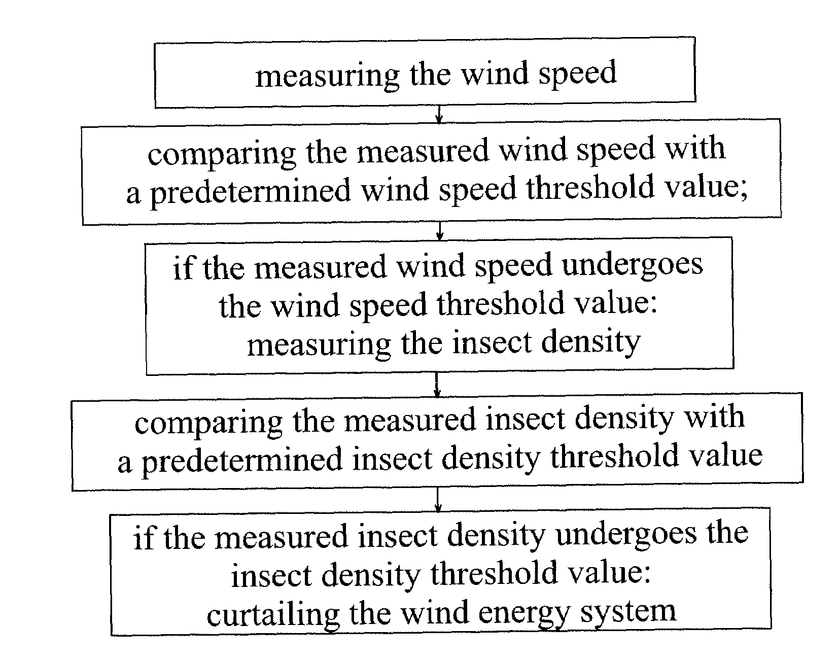
The invention relates to wind energy systems. A wind energy system is provided having an insect sensor. The insect sensor is adapted for measuring the insect density in the air. Further, a method for operating a wind energy system taking into account the insect density in the air is provided. The wind energy system is curtailed during times with a high insect density. Hence, in periods following times with a high insect density, the wind energy system can be operated without the aero-dynamical performance of the rotor blades being spoiled by smashed insects.

Description

BACKGROUND OF THE INVENTION[0001]The present invention relates to a wind energy system and the operation thereof. In particular, the present invention relates to a wind energy system with improved sensor equipment. Further, the present invention relates particularly to the operation of a wind energy system with increased overall performance.[0002]In particular in summer with low winds after rain, insects such as bugs often fly into the rotor of a wind energy system and splatter on the leading edge of the wind energy system rotor blades thereby soiling lift and reducing output. In order to recover summer performance it is known in the art to wait for rain that may clean the blades from the insects that got caught by the blades. However, waiting for rain is most inefficient particularly at those wind energy systems sites being located in dry regions.[0003]Hence, it is known in the art to provide a wind energy system with blade washing equipment. For instance, blade washing may be star...

Claims


Application Information

Patent Timeline
Patent Type & Authority Applications(United States)
IPC IPC(8): H02P9/00G08B23/00
CPCF03D7/042F03D11/0091Y02E10/723F05B2270/80Y02E10/722F05B2270/32F03D17/00Y02E10/72
Inventor EGGLESTON, ERIC
Owner GENERAL ELECTRIC CO
Learn More