
Manually operated dispenser comprising a protective cap

a dispenser and protective cap technology, applied in the direction of liquid handling, instruments, closures using stoppers, etc., can solve the problems of heavy dispensers and therefore inconvenient to carry, and achieve the effect of overcompensating drawbacks and deficiencies

Active Publication Date: 2009-06-04
SILGAN DISPENSING SYST HEMER GMBH
View PDF10 Cites 6 Cited by
  • Summary
  • Abstract
  • Description
  • Claims
  • Application Information

AI Technical Summary

Benefits of technology

[0006]The invention solves the problems and overcomes the drawbacks and deficiencies of prior art dispensers by providing a dispenser which has a protective cap which can be unfolded and can be folded shut, comprises two protective-cap halves and is fastened captively to the dispenser head. The protective-cap halves, which are designed as wings matched in terms of shape, are connected to the pump head via spring hinges on the end edges of the gripping surfaces. The use of spring hinges not only ensures a long service life but also creates the possibility of providing a lightweight protective cap. In addition, coupling the protective-cap halves to the end edges of the gripping surfaces permits the protective cap to be designed in the form of a covering, which is matched in terms of shape, of an entire head side of a dispenser.
[0007]Furthermore, it is advantageous that the protective cap which can be unfolded does not require any substantial change in design of the pump head. The protective cap can simply be attached. The dispensing section and the protective cap may even be injection molded in one part.

Problems solved by technology

However, the transmission of the operating pressure via the wings to the pump head makes stable supporting elements necessary, as a result of which the dispenser is heavier and is therefore inevitably less handy.

Method used


Image

  • Manually operated dispenser comprising a protective cap
  • Manually operated dispenser comprising a protective cap
  • Manually operated dispenser comprising a protective cap

Examples


Embodiment Construction

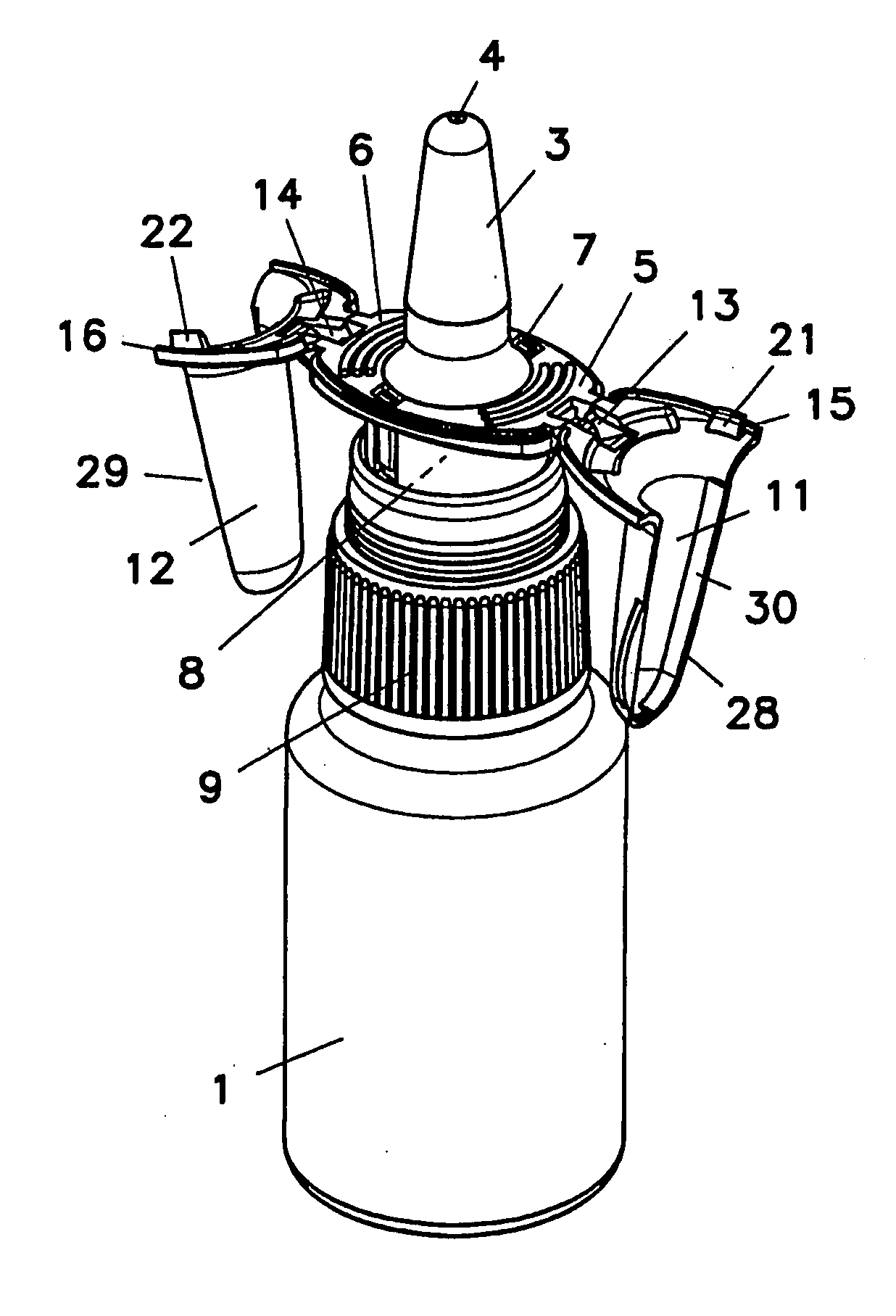
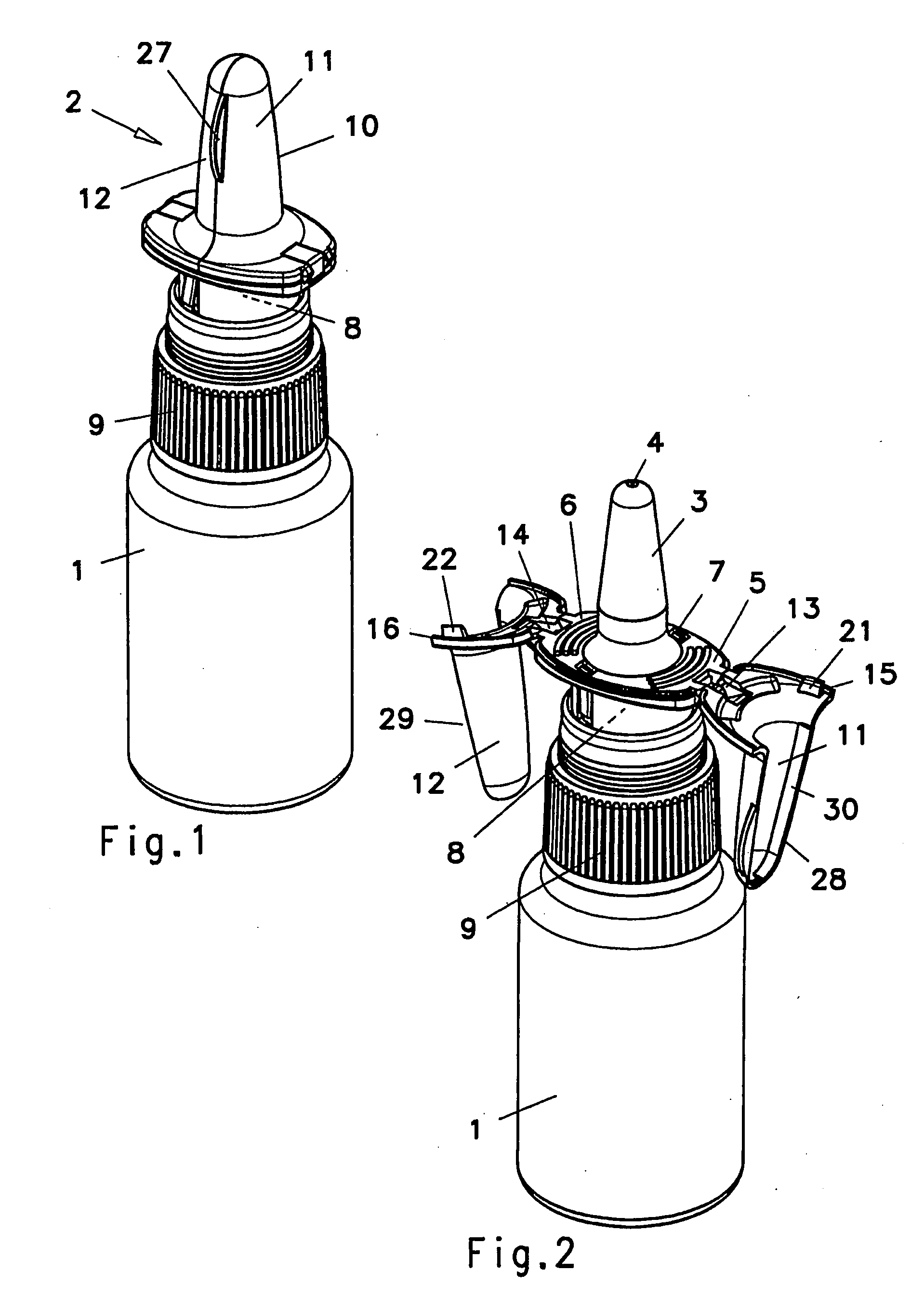
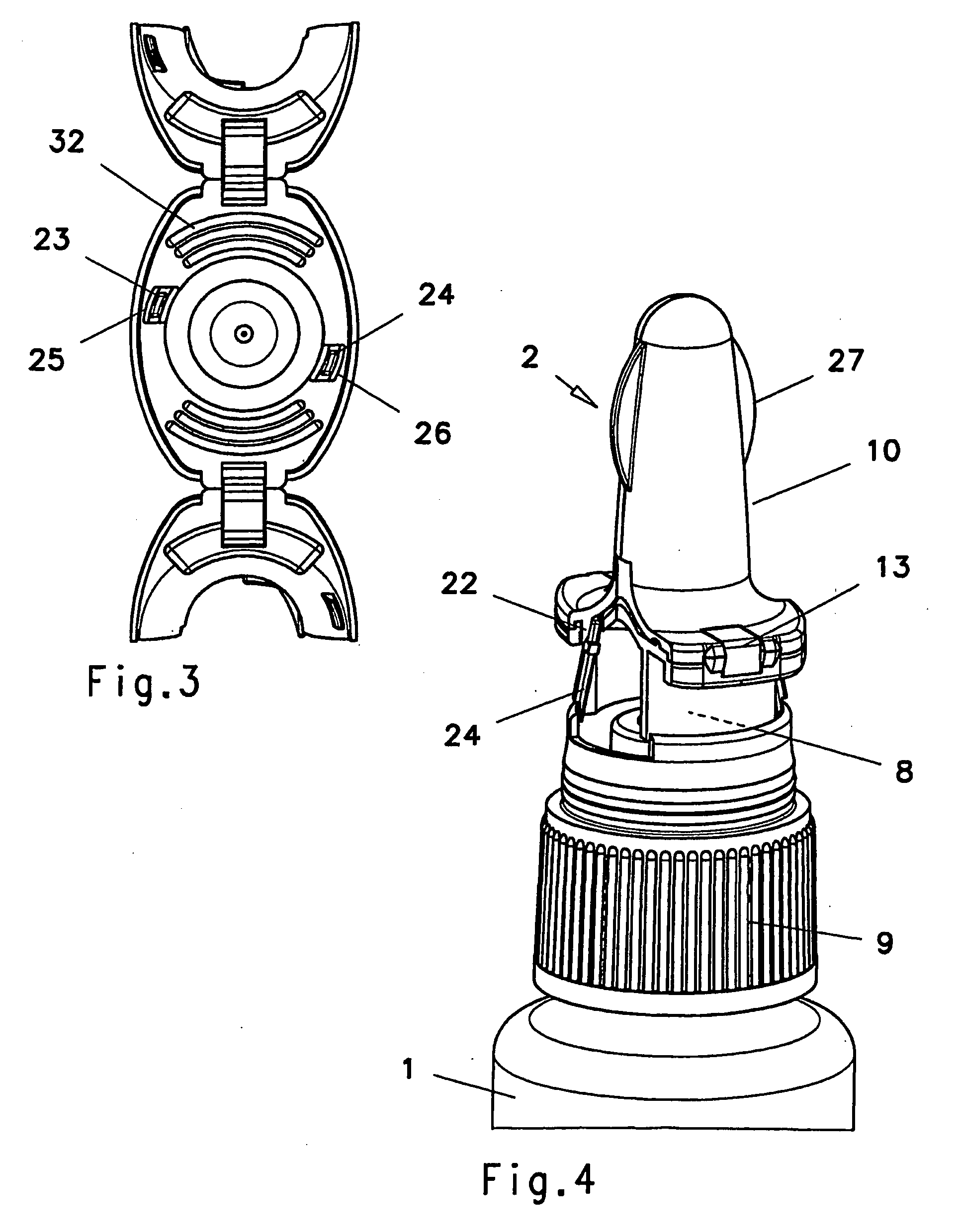
[0015]Referring now to the drawings wherein like reference numerals designate corresponding parts throughout the several views, FIGS. 1 and 2 show a manually operated dispenser for flowable media, with a container 1 having a supply chamber and a pump head 2 which can be fastened thereto. The pump head 2 comprises a dispensing section with a nozzle-shaped nasal adapter 3 which has an outlet opening 4 designed as a spray diffuser at the head end. Gripping surfaces 5, 6 protruding laterally from the nasal adapter 3 extend on opposite sides. The gripping surfaces 5, 6 can be connected via a central section 7.

[0016]The nasal adapter 3 is assembled to a plunger 8 of a sliding plunger pump 9 which is fastened to the container 1. To dispense a charge in one or more strokes, nasal adapter 3 and container 1 are moved in relation to each other by resting at least one finger on the gripping surfaces 5, 6.

[0017]The pump head 2 furthermore comprises a protective cap 10 which comprises two halves ...


PUM


Abstract

A manually operated dispenser for flowable media, having a container which has a supply chamber, and a pump head which can be fastened thereto and has a dispensing section with a nozzle-shaped nasal adapter having an outlet opening designed as a spray diffuser, and gripping surfaces protruding laterally from the nasal adapter, and having a protective cap, which has two wings which can be unfolded and are matched in terms of shape, for the nasal adapter, the gripping surfaces having, on opposite sides, end edges which are connected as a single piece to a wing of the protective cap via a respective spring hinge, and the wings have base surfaces which overlap the gripping surfaces.

Description

BACKGROUND OF INVENTION[0001]a. Field of Invention[0002]The invention relates to a manually operated dispenser for flowable media, having a container which has a supply chamber, and a pump head which can be fastened thereto.[0003]b. Description of Related Art[0004]EP 1 132 143 A2 discloses a manually operated dispenser comprising a protective cap in order to protect a nasal adapter against soiling or damage while not in use. The protective cap comprises two protective-cap halves which are fastened as wings, which are matched in terms of shape, to the nozzle-shaped dispensing section of the nasal adapter via hinges. In the unfolded state, the wings form gripping surfaces for operating the pump head. A dispenser of this type has the advantage of a slender constructional shape. However, the transmission of the operating pressure via the wings to the pump head makes stable supporting elements necessary, as a result of which the dispenser is heavier and is therefore inevitably less handy...

Claims


Application Information

Patent Timeline
Patent Type & Authority Applications(United States)
IPC IPC(8): B67D5/06B05B11/00B65D88/54B67D7/06A61M15/08
CPCB05B11/0032A61M15/08
Inventor WELP, GISBERT
Owner SILGAN DISPENSING SYST HEMER GMBH
Learn More