Eureka AIR delivers breakthrough ideas for toughest innovation challenges, trusted by R&D personnel around the world.

Energy-Regulating System for a Vehicle

a technology of energy regulation and vehicle, applied in the direction of position/direction control, electric energy management, special data processing applications, etc., can solve the problems of additional input or consumption of energy, and achieve the effect of efficiently minimizing the economic and environmental impact of electrical traction or propulsion vehicles

Active Publication Date: 2009-05-28
SIEMENS MOBILITY SAS
View PDF6 Cites 38 Cited by
  • Summary
  • Abstract
  • Description
  • Claims
  • Application Information

AI Technical Summary

Benefits of technology

[0007]It is accordingly an object of the invention to provide an energy-regulating system for a vehicle which overcomes the above-mentioned disadvantages of the prior art devices of this general type, which efficiently minimizes the economical and environmental impact of an electrical traction or propulsion vehicle and is suitable for public transport.

Problems solved by technology

External factors such as wind or cold can also influence consumption or additional input of energy in the balance.

Method used


Image

  • Energy-Regulating System for a Vehicle
  • Energy-Regulating System for a Vehicle
  • Energy-Regulating System for a Vehicle

Examples


Embodiment Construction

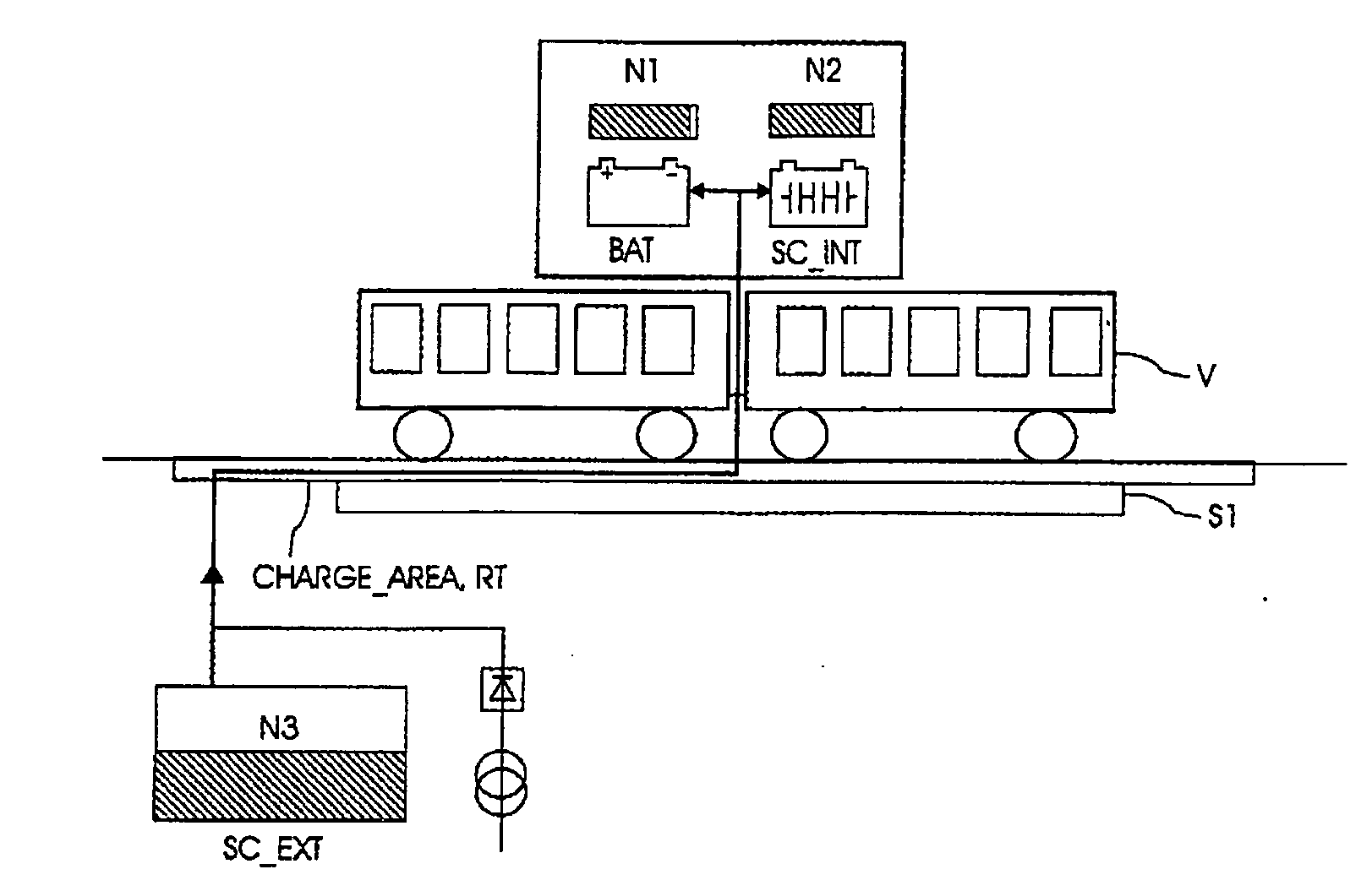
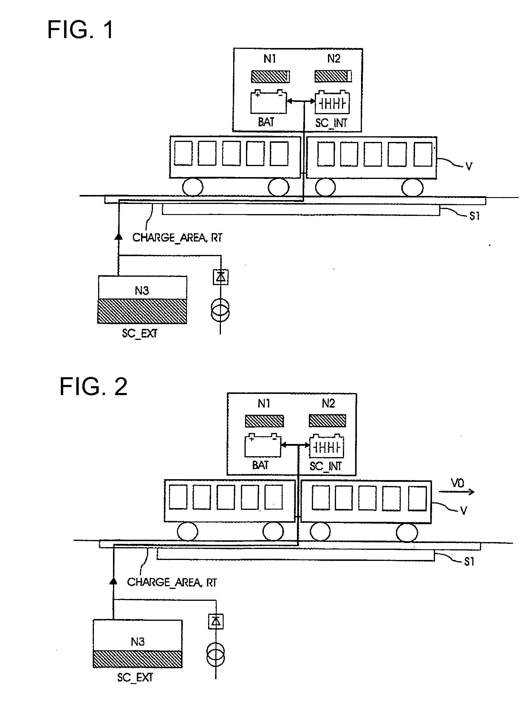
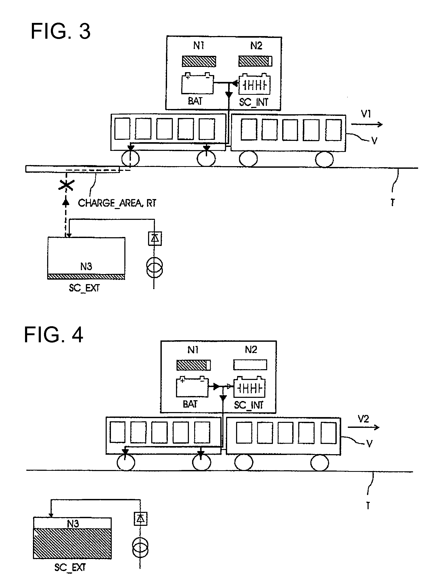
[0038]Referring now to the figures of the drawing in detail and first, particularly, to FIGS. 1-6 thereof, there is shown an example of an energy-regulating system described previously as well as an operating process of the system for a vehicle V on a run T between a departure station S1 according to FIGS. 1 and 2 and an arrival station S2 according to FIGS. 5 and 6. The stations S1, S2 contain for instance a platform (along the length of stations S1, S2) for the passengers such as a classical station stop for a subway, a tramway, a bus, etc. A high-power electrical storage device, here a super-capacitor SC_INT with a charge level N2 (no hatching=minimum level; if hatching=higher level), is placed on board the vehicle supplying the vehicle with traction power. In this example, a battery BAT (with high mass energy contrary to the super-capacitor) with a charge level N1 is also placed on board the vehicle. Here, the vehicle contains two cars of which one at least is a tractor or prope...


PUM


Abstract

An energy-regulating system for a vehicle, suitable for use in a mass transportation system between a departure station and an arrival station along a predetermined route, has advantageously a high-power electrical storage device placed on board the vehicle, supplying power to the vehicle, at least during acceleration. The energy recovered during braking of the vehicle is stored in the storage device. At least the departure station includes an electrical charging area capable of charging the storage device of the vehicle and activated in a charging mode as soon as the residual energy of the storage device of the vehicle is below a variable threshold dependent on an early estimate of the energy balance of the vehicle at least up to the arrival station.

Description

CROSS-REFERENCE TO RELATED APPLICATIONS[0001]This is a continuing application, under 35 U.S.C. § 120, of copending international application PCT / EP2007 / 003237, filed Apr. 12, 2007, which designated the United States; this application also claims the priority, under 35 U.S.C. § 119, of European patent application EP 06290825.6, filed May 19, 2006; the prior applications are herewith incorporated by reference in their entirety.BACKGROUND OF THE INVENTIONField of the Invention[0002]The present invention relates to an energy-regulating system for a vehicle, suitable to public transport between a departure station and an arrival station, separated by a predetermined run. The energy-regulating system contains a high-power electrical storage device, placed on board the vehicle. Energy recovered during braking of the vehicle is stored in the storage device. An electrical battery of high mass energy is placed on board the vehicle.[0003]A global approach of energy management is provided with ...

Claims


Application Information

Patent Timeline
IPC IPC(8): G06F19/00B60L50/15
CPCB60L1/003B60M3/06B60L9/00B60L11/005B60L11/123B60L11/1816B60L11/182B60L11/1837B60L11/1887B60L15/2045B60L2230/26B60L2230/28B60L2230/30B60L2260/54B60L2260/56B60M1/36Y02T10/6217Y02T10/7005Y02T10/7022Y02T10/7077Y02T10/7088Y02T10/7283Y02T10/92Y02T90/121Y02T90/122Y02T90/128Y02T90/14Y02T90/34B60L2200/18B60L2200/26B60L5/42Y02T10/72B60L50/40B60L50/61B60L53/12B60L53/32B60L58/40B60L53/56B60L53/54B60L53/53B60L50/53Y02T10/62Y02T10/70Y02T10/64Y02T10/7072Y02T90/12B60L50/50Y02T90/40
Inventor CHATTOT, ERIC
Owner SIEMENS MOBILITY SAS
Why Eureka
Eureka Blog
Learn More