
Method of Calibrating a Sensor System

Inactive Publication Date: 2009-05-21
ROBERT BOSCH GMBH
View PDF8 Cites 9 Cited by
  • Summary
  • Abstract
  • Description
  • Claims
  • Application Information

AI Technical Summary

Benefits of technology

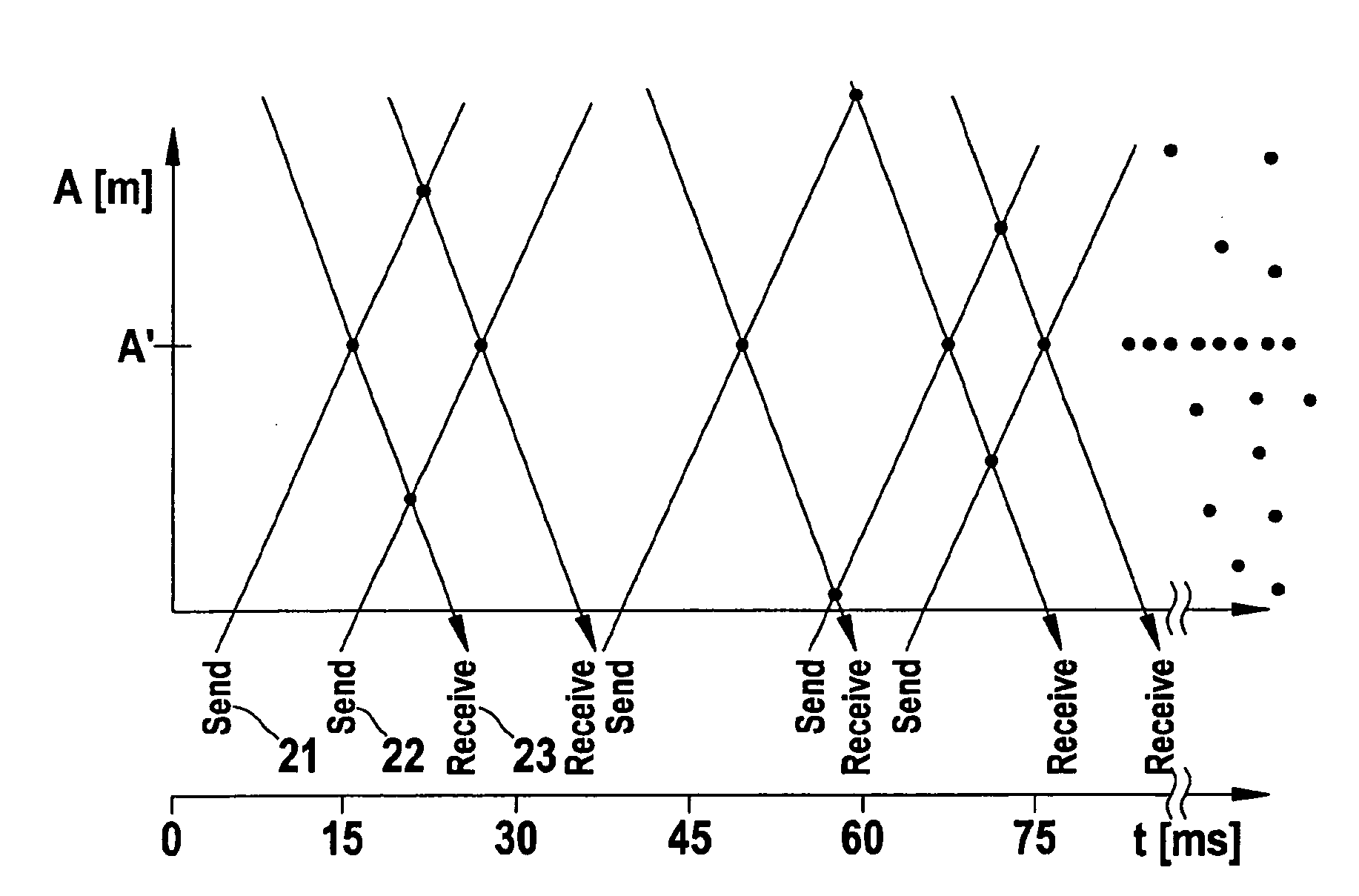
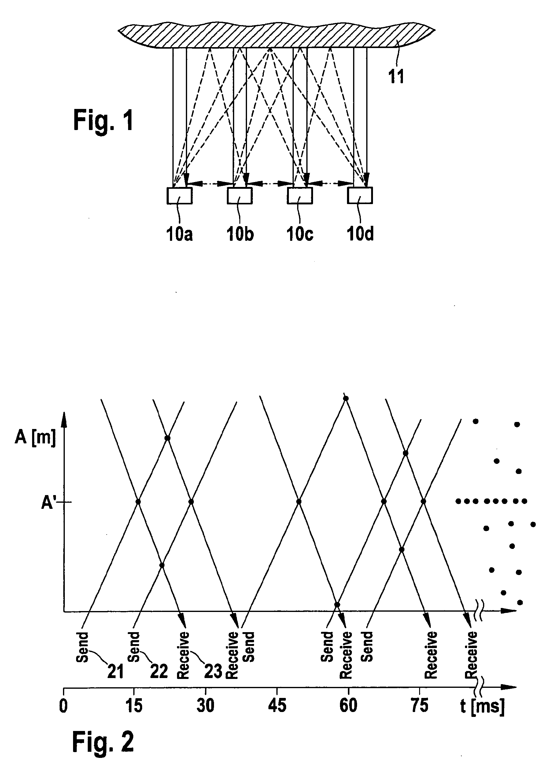
[0027]It is advantageous in this instance, if the receive signal received by the receiver, from which the direct crosstalks generated by the transmitter are filtered out, corresponds to a send signal generated by the transmitter while using stochastic coding. A method is thus provided which makes possible the automatic calibration of transmitter-receiver systems which are operated on the basis of stochastic coding.

Problems solved by technology

The available parking space becomes tighter, and the search for a suitable parking space stresses the driver, in addition to ever increasing traffic.
However, in stochastic coding, direct crosstalks have an interfering effect, since they are not able to be determined directly, but are only detectable after receiving and decoding the receive signal as well as classifying same (forming a histogram).
This manual determination of the signal propagation times takes place at the plant, or, in the case of retrofitting of a parking assistance system, during the course of this retrofitting, which is connected with additional costs.
There is also the problem that, because of the temperature dependence of the speed of sound, the signal propagation times between the individual sensors are also temperature dependent.
The speed of sound increases with increasing temperature, and thus brings about shorter signal propagation times. At extremely high or low temperatures, the actual signal propagation times no longer correspond to the values measured and stored before, so that the filter mask for filtering the direct crosstalks becomes ineffective.
This may in turn lead to erroneous interpretations of the receive signal, and consequently to erroneous parking information to the driver.

Method used


Image

  • Method of Calibrating a Sensor System
  • Method of Calibrating a Sensor System
  • Method of Calibrating a Sensor System

Examples


Embodiment Construction

[0037]Unless specifically mentioned otherwise, identical or functionally equivalent elements have been provided with the same reference numerals in the figures of the drawings.

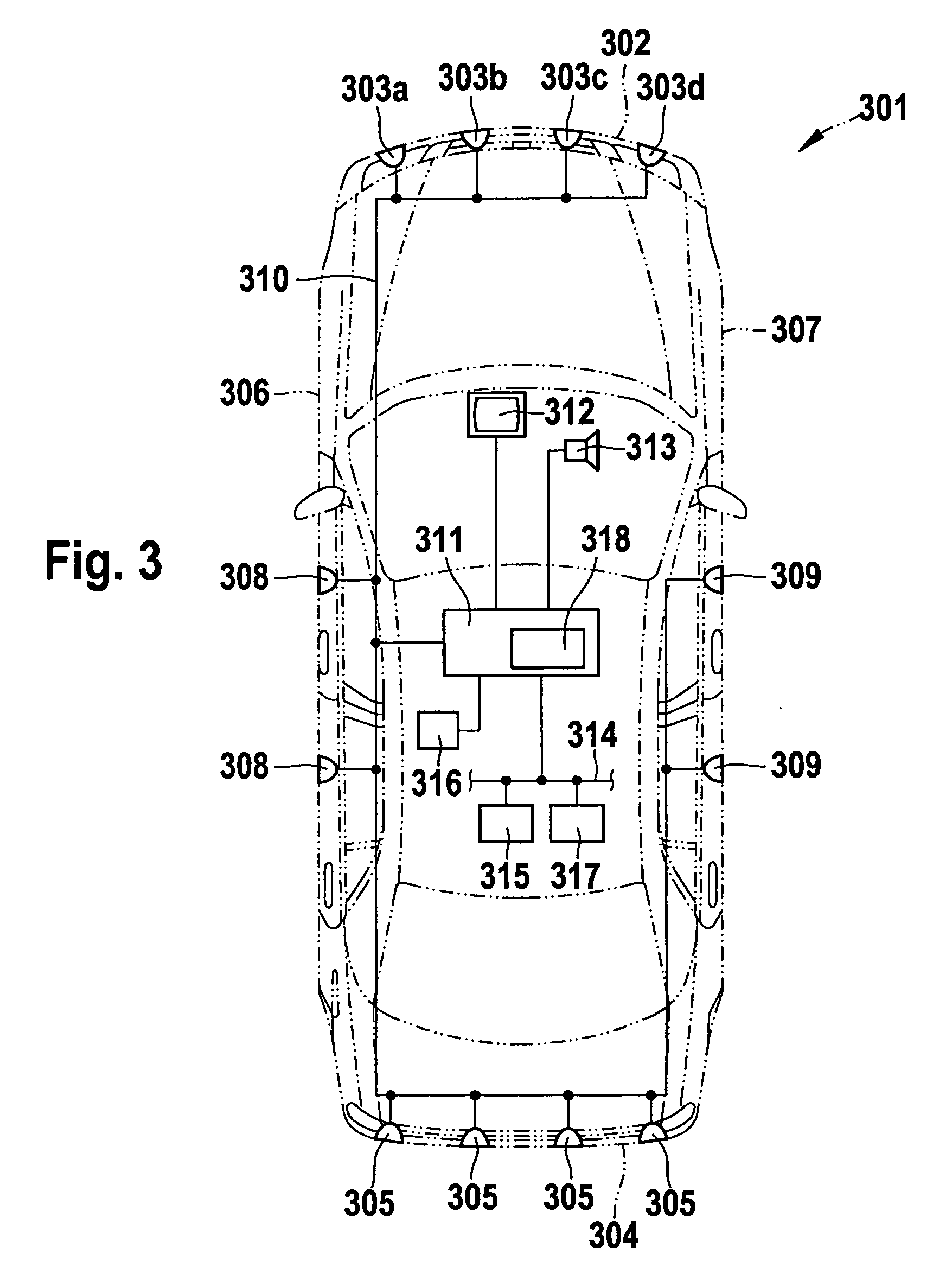
[0038]A motor vehicle 301 is schematically shown in FIG. 3. Distance sensors 303a-303d are situated at the vehicle's front end 302. Distance sensors 305 are also situated at rear end 304 of the vehicle. Lateral distance sensors 308 are provided at left side 306 of the vehicle. Lateral distance sensors 309 are provided at right side 307 of the vehicle. The distance sensors are used for measuring distances from obstacles in the vehicle's surroundings. In the present specific embodiment, distance sensors 303, 305, 308, 309 are developed as ultrasound sensors. They may also, however, measure distances based on another measuring principle, such as radar signals. Distance sensors 303, 305, 308, 309 supply their sensor signals via a data bus 310 to a program-controlled device 311 (for instance, a microprocessor, micr...


PUM


Abstract

A method for calibrating a sensor system having transmitters and receivers mounted on a vehicle at a distance from one another, and for measuring the distance of the vehicle from a roadway boundary, by a) sending a send signal at a first time, using a transmitter of the sensor system, b) converting the received send signal to a receive signal using a receiver of the sensor system, and establishing a second time at which the receive signal exceeds a certain threshold value, c) determining the propagation time of the send signal from the transmitter to the receiver from the difference in time between the second time and the first time, d) repeating a) to c) cyclically for a certain number of cycles, e) determining a frequency distribution of the propagation times determined in c), and f) generating a sensor distance value, which correlates with the sensor propagation time between the transmitter and the receiver, with the frequency distribution determined in e).

Description

FIELD OF THE INVENTION[0001]The present invention relates to a method for calibrating a sensor system having transmitters and receivers mounted on a vehicle at a distance from one another, for measuring the distance of the vehicle from a roadway boundary, a method for recording the sensor condition of a sensor mounted on a vehicle, as well as a parking assistance system and a distance measuring device of a vehicle for measuring the distance of the vehicle from a roadway boundary.BACKGROUND INFORMATION[0002]The increase in traffic density and more and more construction taking up free areas are reducing traffic space continuously, in particular in conurbation centers. The available parking space becomes tighter, and the search for a suitable parking space stresses the driver, in addition to ever increasing traffic. For that reason, among others, semiautonomous parking aid systems (SPA) have been developed, which are intended to support the driver during parking. The decision as to whe...

Claims


Application Information

Patent Timeline
IPC IPC(8): G01S7/40G01S15/931
CPCG01S7/52004G01S15/931G01S15/878G01S7/52006
Inventor WIELAND, OLIVER
Owner ROBERT BOSCH GMBH
Learn More