
Power Management of an Electronic System

a technology of power management and electronic systems, applied in the direction of power supply for data processing, liquid/fluent solid measurement, instruments, etc., can solve the problems of system power constraints and unused power availability, and achieve the effects of reducing device power limits, limiting power consumption, and increasing device power limits

Active Publication Date: 2009-05-14
LENOVO GLOBAL TECH INT LTD
View PDF21 Cites 96 Cited by
  • Summary
  • Abstract
  • Description
  • Claims
  • Application Information

AI Technical Summary

Benefits of technology

[0010]Other embodiments, aspects, and advantages of the invention will be apparent from the following description and the appended claims.

Problems solved by technology

For example, power constraints on the system as a whole need to be considered, in addition to managing power consumption to the servers individually.
Furthermore, the aggregate margins between each server's power cap and its actual power consumption represents unused power availability.

Method used


Image

  • Power Management of an Electronic System
  • Power Management of an Electronic System
  • Power Management of an Electronic System

Examples


Embodiment Construction

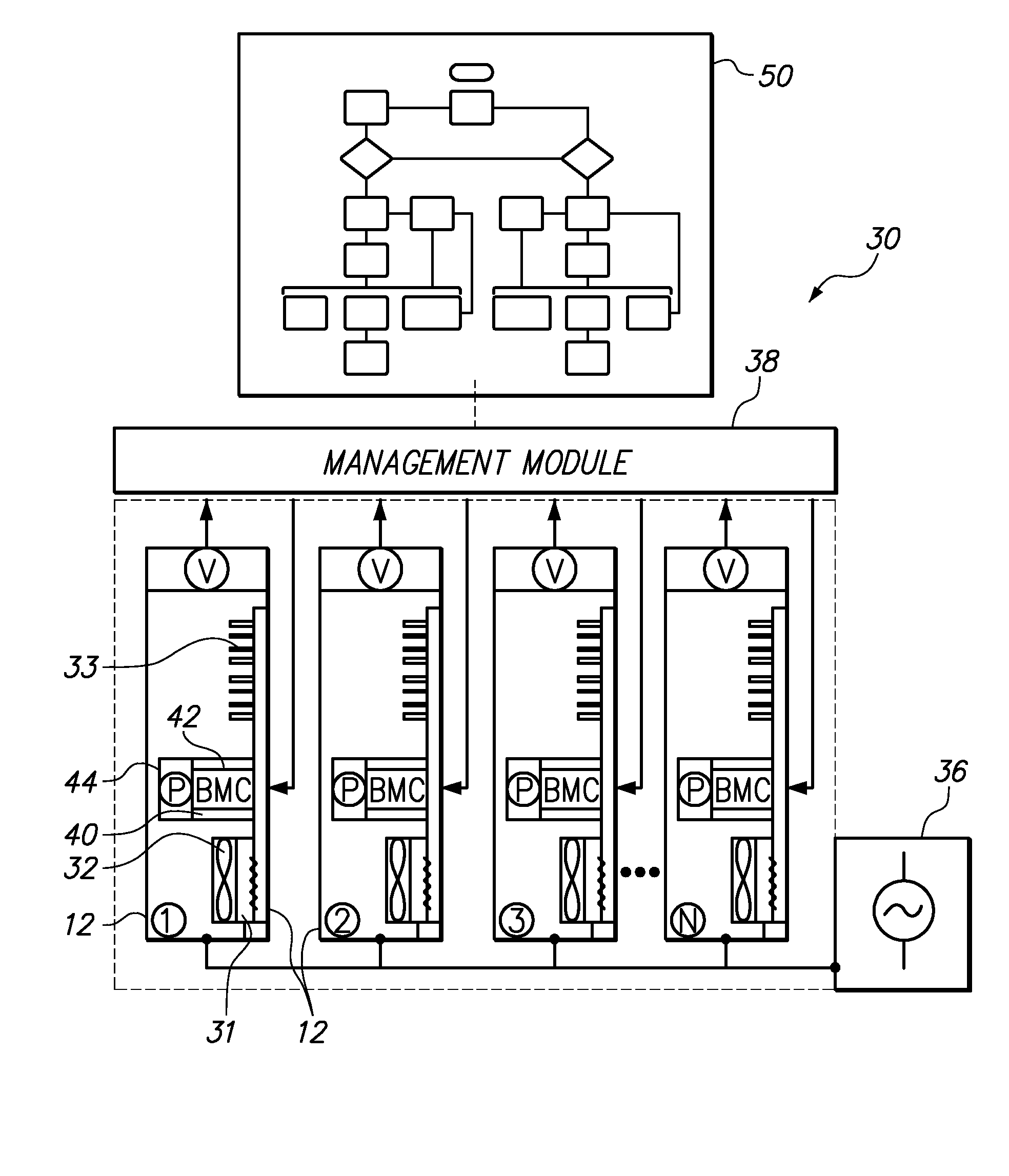
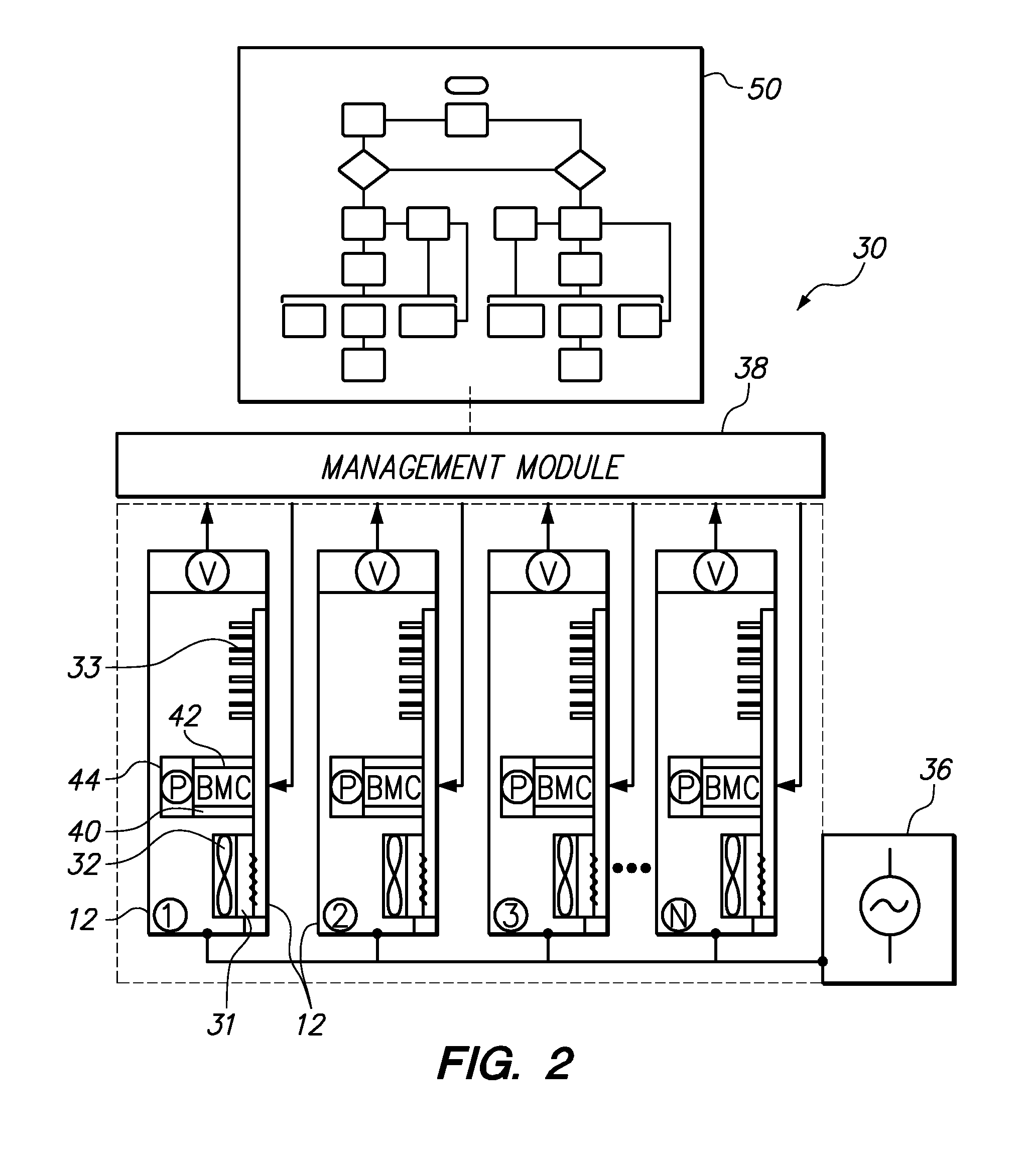
[0016]The present invention provides a system, method, and computer program product for managing power in an electronic system having a plurality of power-consuming electronic devices. A power limit for a group of devices is provided and dynamically allocated among the devices within the group such that each device is operated within a device power limit. The device power limits are individually, dynamically adjusted in such a way that the sum of the device power limits is substantially equal to the group power limit. The invention is particularly applicable in the realm of computer systems having a plurality of rack-mounted servers and supporting hardware devices. Thus, the invention will be discussed extensively in the context of managing power to a computer system that includes a network of servers. One skilled in the art having benefit of this disclosure will appreciate that the invention may also be applied to other electronic systems having multiple power-consuming electronic ...


PUM


Abstract

A variable group power limit is enforced to limit the net power consumption of a group of devices in a computer system, and a variable device power limit enforced on each device is independently adjustable to satisfy the current group power limit. The device power limits are dynamically selected according to a power management method that selectively reduces the device power limits of lower-utilization devices and increases the device power limits of higher-utilization devices.

Description

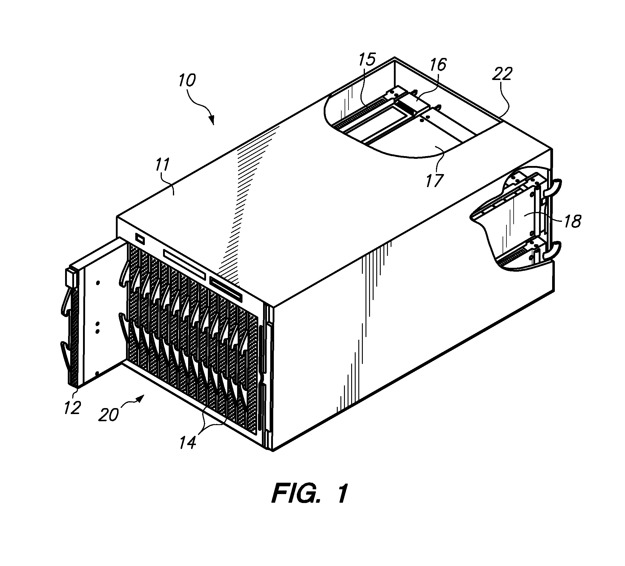
BACKGROUND OF THE INVENTION[0001]1. Field of the Invention[0002]The present invention relates to power management in an electronic system such as a computer system having multiple energy-consuming electronic devices.[0003]2. Description of the Related Art[0004]Servers and other computer hardware are often grouped together on a rack to conserve space and place the servers and infrastructure in a central location for access by an administrator. Managing these “rack systems” can be less difficult and less expensive than separately administering a multitude of scattered servers. A variety of rack system designs are available in the market, and range in size and density. Some rack systems may be built around servers that are self-supporting in that each server has an individual chassis, on-board power supply, cooling fan, and other support devices. The self-supporting servers may be grouped in a rack or tower configuration and networked to each other and to client computers. A higher den...

Claims


Application Information

Patent Timeline
IPC IPC(8): G06F1/32
CPCG06F1/3203
Inventor BREY, THOMAS M.PIAZZA, WILLIAM JOSEPH
Owner LENOVO GLOBAL TECH INT LTD
Learn More