
Display apparatus

a technology of display apparatus and spherical support, which is applied in the direction of instruments, spectacles/goggles, non-optical parts, etc., can solve the problems of user inconvenience, headaches, and the relative preponderance of the weight of the display apparatus in the region of the nose support,

Active Publication Date: 2009-05-14
CARL ZEISS SMT GMBH
View PDF5 Cites 0 Cited by
  • Summary
  • Abstract
  • Description
  • Claims
  • Application Information

AI Technical Summary

Benefits of technology

[0006]The present invention is directed to a display apparatus comprising an image module and a spectacle-like frame wherein the display apparatus includes at least one of the temples having a holding element shiftably mounted thereon, which holding element comprises a first portion extending downwards from the temple. The shiftability of the holding element allows individual, optimal positioning, of the holding element behind the ear in the region of the temporal bone for each user. In particular, the holding element is shiftable in the longitudinal direction of the temple. This allows the position of the holding element to be individually adapted for each user such that the holding element abuts against the temporal bone region directly behind the ear when the display apparatus is mounted.
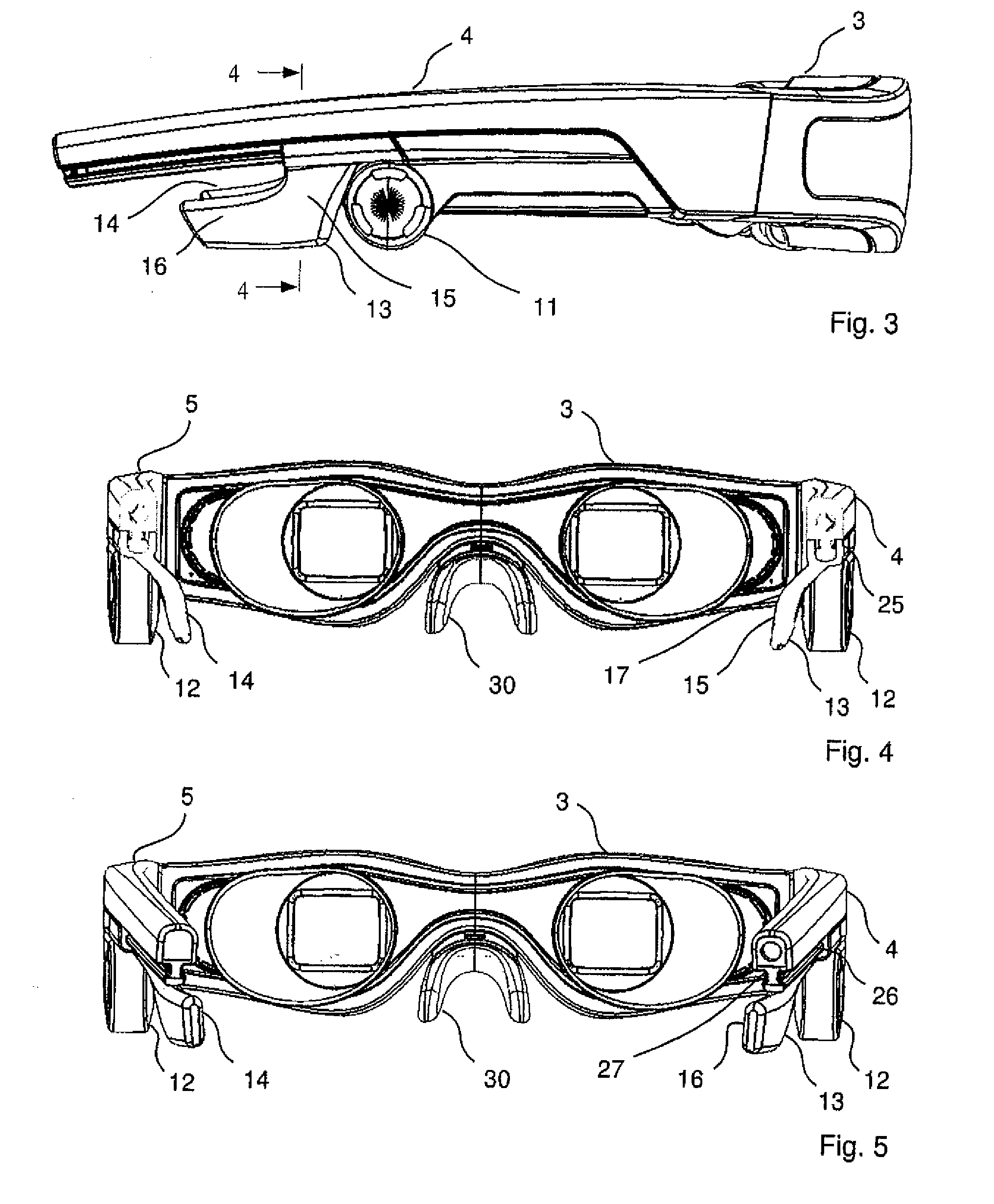
[0008]The holding element's internal surface, which abuts against the user's head behind the ear when the display apparatus is mounted on the user's head, has a convex curvature at first, in the region of the first portion, in a direction pointing away from the temple (i.e. downwards from the temple), which convex curvature then passes over into a concave curvature. Further, the internal surface can have a convex curvature in the region of the second portion, in a direction extending away from the first portion, which convex curvature then passes into a concave curvature. The above-described design of the internal surface in the region of the first portion allows optimum engagement of the holding element by the groove behind the ear (the region of the temporal bone behind the auditory canal). Due to the convex curvature in the region of the second portion, this leads to the holding element being virtually hooked to the groove behind the ear. The adjoining convex curvature of the second portion is an adaptation to the shape of the head which tapers towards the rear again, thus achieving a positive wedge effect counteracting a forward sliding movement of a display apparatus over the nose.
[0010]Together, the two portions of the holding element form a substantially L-shaped arrangement. This arrangement provides a holding element that is compact, on the one hand, and can ensure optimum support of the display apparatus, on the other hand.
[0012]Further, the holding element is preferably shiftable towards the temple such that shifting is possible only in a longitudinal direction of the temple. For example, shifting only along a longitudinal direction prevents rotation about the longitudinal direction or axis. The holding element can comprise a slide, which engages in two guide grooves that extend in a longitudinal direction on both sides of the temple. The holding element can be relatively thick and rigid.
[0013]Further, the holding element can be elastically pretensioned in a direction transverse to the temple. If the holding element is rigid, spring pretension can be achieved. As an alternative, it is possible for the elastic pretension to be achieved by the inherent elasticity of the holding element.

Problems solved by technology

Due to the image module being carried by the spectacle-like frame, these head-mounted display apparatuses have the problem that the display apparatus has a relative preponderance of weight in the region of the nose support.
Therefore, such HMD apparatuses can easily slip down from the nose, so that the user can no longer perceive the image optimally.
In particular, headaches may be caused by the HMD apparatus sitting too low on the nose.
However, this is problematic in that the user's hairdo may be indented in the region of the holding band under certain circumstances.
Further, hairs may get caught in the holding band.
In many cases the holding band is under too much tension, so that an unpleasant pressure is exerted on the user's nose and head by the display apparatus in the long run.
This pressure on the nose and head can also lead to headache and other discomfort.

Method used


Image

  • Display apparatus
  • Display apparatus
  • Display apparatus

Examples


Embodiment Construction

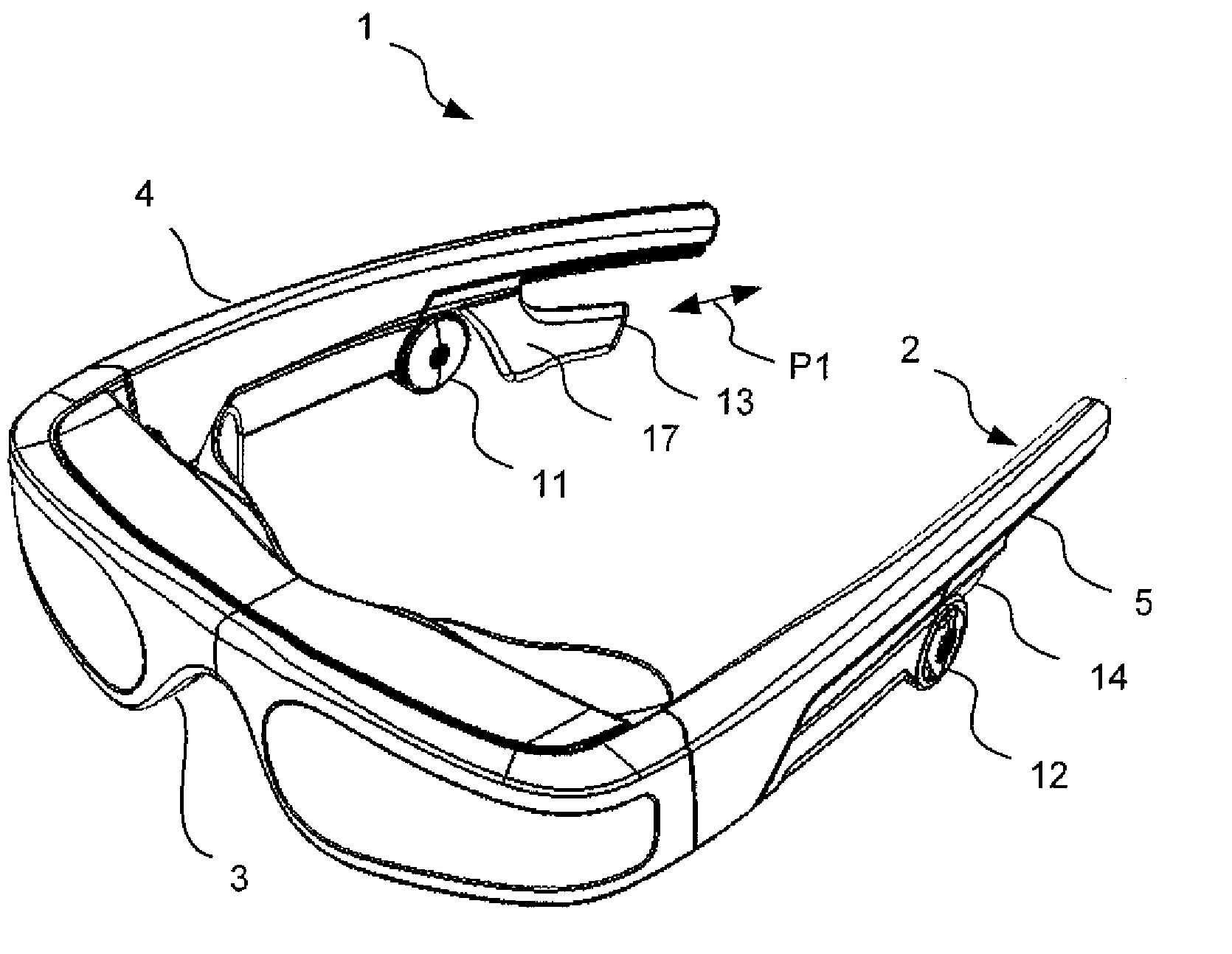
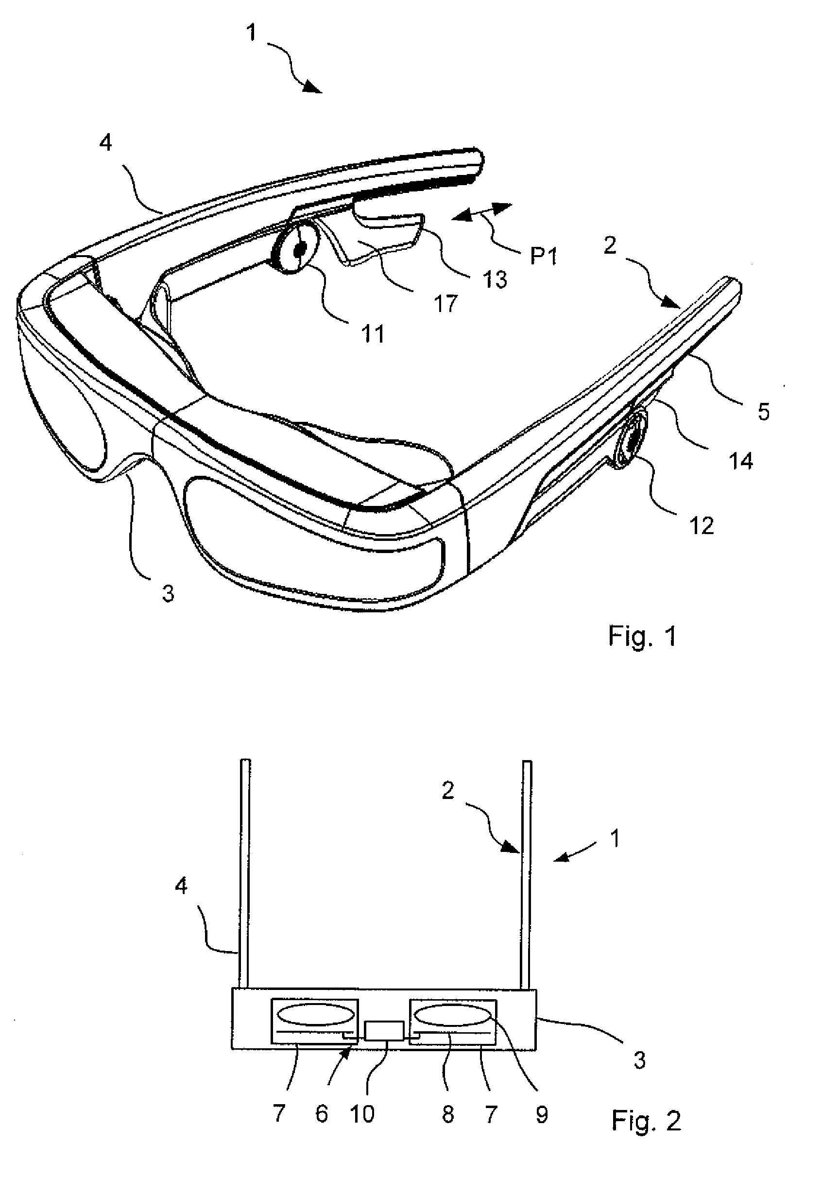
[0028]In the embodiment shown in FIGS. 1-10, the display apparatus 1 according to the invention comprises a spectacle-like frame 2, including a front portion 3 which comprises a nose support 30, and two temples 4, 5.

[0029]As is evident from the schematic representation in FIG. 2, the front portion 3 contains an image module 6, which comprises, for each eye of a user wearing the display apparatus 1, a display unit 7 with an image-generating element 8 and imaging optics 9. The image module 6 further includes a control unit 10, which controls the display units 7 on the basis of predetermined image data so as to generate the desired images. For example, the image data can be supplied to the control unit 10 via a signal line, not shown, which extends through the right temple 4.

[0030]Each temple 4, 5 has mounted to it an earphone 11, 12 which can be swiveled down and whose spacing from the front portion 3 can be adjusted. Further, each temple has a holding element 13, 14 shiftably mounted...


PUM


Abstract

A display apparatus which comprises an image module for generating an image, a spectacle-like frame which carries the image module, and wherein the spectacle-like frame comprises a front portion with a nose support, as well as two lateral temples mounted to the front portion. At least one of the temples has shiftably mounted to it a holding element. The holding element comprises a first portion extending downwards from the temple, and a second portion connected with the lower end of the first portion, the second portion extending from the lower end of the first portion in a direction pointing away from the front portion.

Description

PRIORITY APPLICATION[0001]The current application claims the benefit of priority to German Patent Application No. DE 10 2007 053 282.4 filed on Nov. 8, 2007. Said application is incorporated in its entirety by reference herein.FIELD OF THE DISCLOSURE[0002]The present invention relates generally to the field of display apparatuses. More specifically, the present invention relates to a display apparatus comprising an image module for generating an image and a spectacle-like frame, which carries the image module and has a front portion with a nose support, as well as two lateral temples mounted to the front portion. Such display apparatuses are often referred to as HMD apparatuses (Head-Mounted Display apparatuses).BACKGROUND OF THE INVENTION[0003]Generally for head-mounted displays (HMD's), the image module is carried by the spectacle-like frame and can be heavy, as compared to the spectacle-like frame. Due to the image module being carried by the spectacle-like frame, these head-moun...

Claims


Application Information

Patent Timeline
IPC IPC(8): G09G5/00
CPCG02B27/017G02B27/0176G02C5/20G02C5/143G02B2027/0154
Inventor KARUTZ, FRANK-OLIVERROTTENKOLBER, BIRGITWURSCHER, NORBERTENGLER, BERTOLDBECK, KLAUS
Owner CARL ZEISS SMT GMBH
Learn More