
Electromagnetic shock absorber for vehicle

Active Publication Date: 2009-05-14
TOYOTA JIDOSHA KK
View PDF5 Cites 108 Cited by
  • Summary
  • Abstract
  • Description
  • Claims
  • Application Information

AI Technical Summary

Benefits of technology

[0004]In the electromagnetic absorber disclosed in the above-identified patent document, a motor housing holding a stator (as a stationary element) is elastically supported by the body-side member, and a motor shaft provided with a rotor (as a rotatable element that is a kind of movable element) is fixedly connected to an externally threaded rod that is held in thread engagement with a nut provided in the wheel-side member. In the thus constructed absorber, it is intended to prevent locking of the absorber upon application of an impact load from the wheel and to effectively cope with vibrations caused by the impact load.

Problems solved by technology

In the electromagnetic absorber disclosed in the above-identified patent document, although the electromagnetic motor per se is supported in an elastic manner, namely, although there is an arrangement for alleviating the vibrations acting on the motor, such a vibration alleviation arrangement is not satisfactorily sufficient.
The above-described problem relating to the vibrations acting on the electromagnetic motor is merely one of problems encountered in the electromagnetic absorber.

Method used


Image

  • Electromagnetic shock absorber for vehicle
  • Electromagnetic shock absorber for vehicle
  • Electromagnetic shock absorber for vehicle

Examples


first embodiment

a) Construction of Electromagnetic Shock Absorber

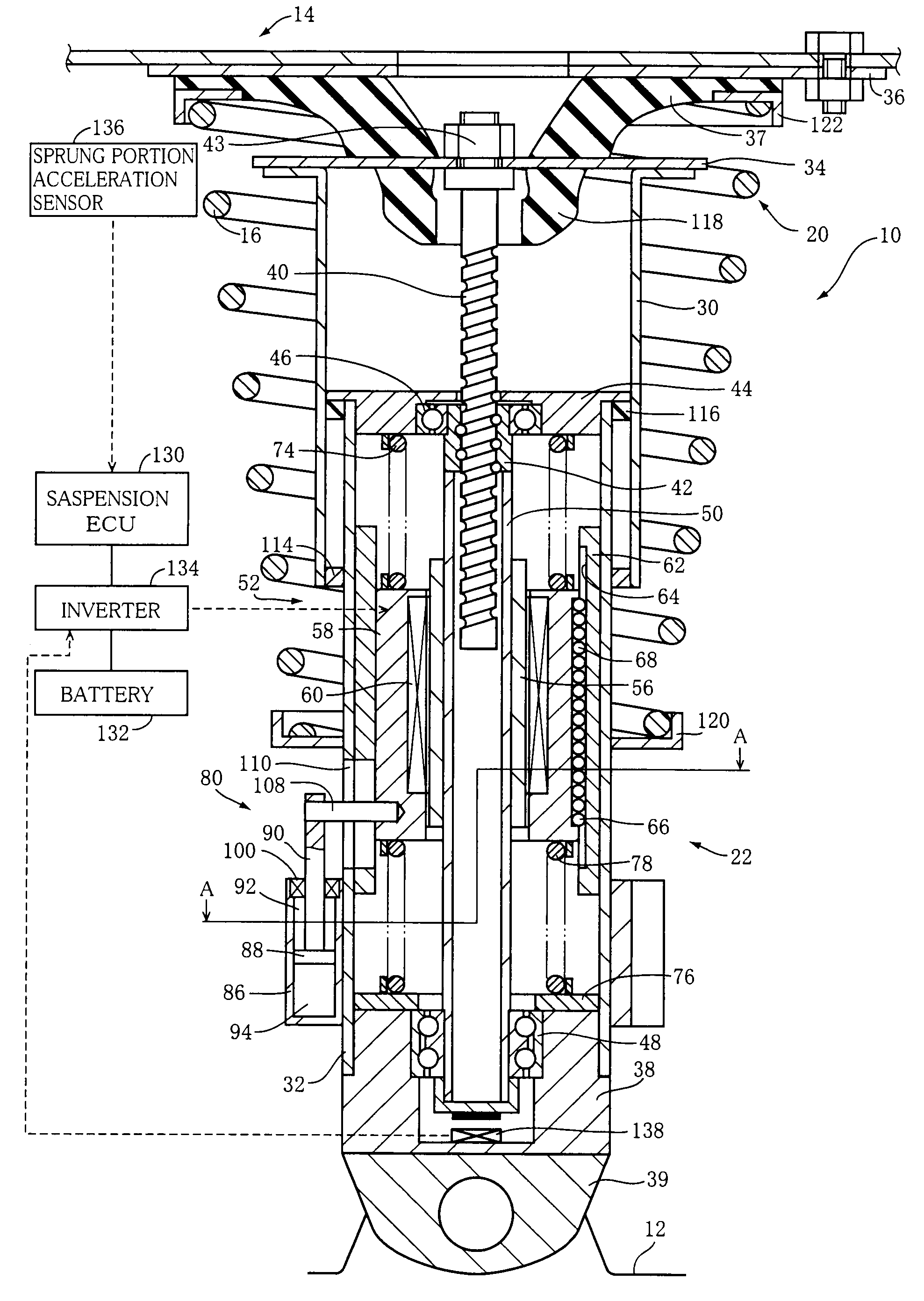
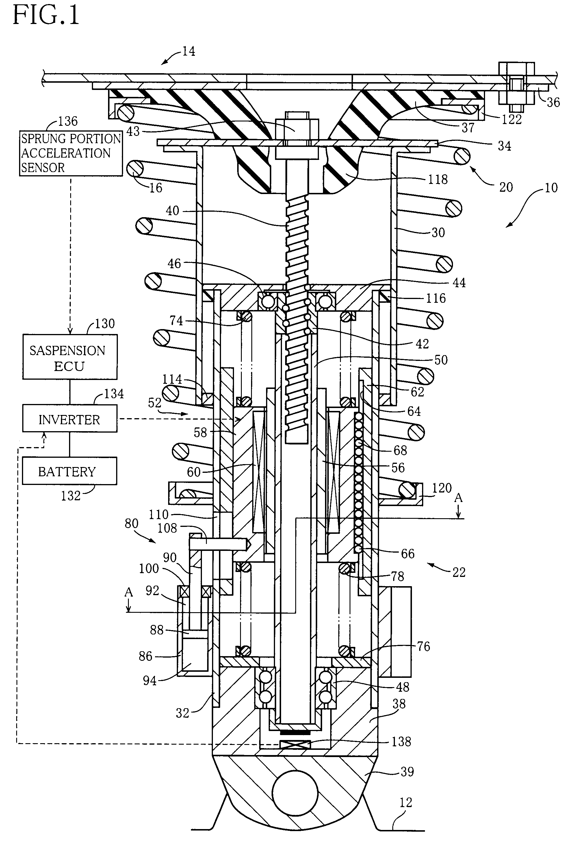
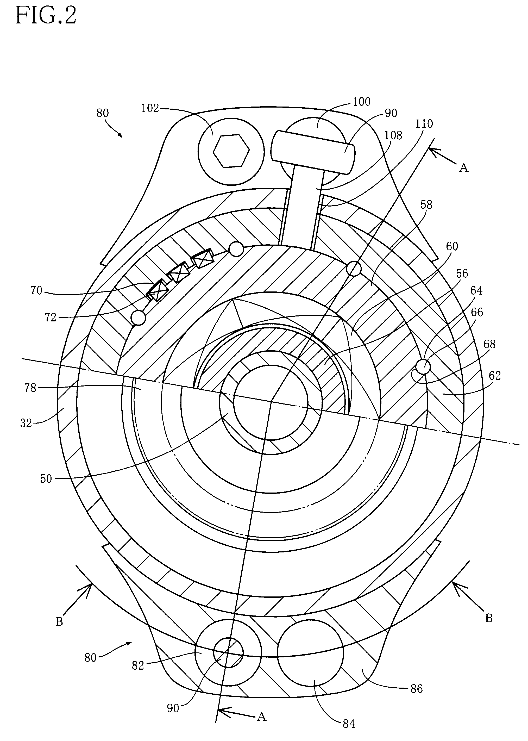
[0056]FIG. 1 shows an electromagnetic shock absorber 10 for a vehicle according to a first embodiment of the invention. This electromagnetic absorber 10 is one of components constituting a suspension system of independent type, and is provided for each of front right, front left, rear right and rear left wheels of the vehicle. The present electromagnetic absorber 10 is disposed between a suspension lower arm (hereinafter abbreviated as “lower arm” where appropriate) 12 and a mount portion 14. The lower arm 12 constitutes a wheel holder that holds the wheel, while the mount portion 14 is provided in a part (an upper portion of a tire housing) of the vehicle body. A suspension device provided for each wheel is constructed to include this electromagnetic absorber 10 and a coil spring 16 as a suspension spring. In the present embodiment, the present electromagnetic absorber 10 is applied in the suspension device using the coil spring as t...

second embodiment

[0074]FIG. 7 shows an electromagnetic shock absorber 200 for a vehicle according to a second embodiment of the invention. The present electromagnetic absorber 200 employs a linear motor, while the electromagnetic absorber 10 of the above-described embodiment is equipped with the rotary motor 52. The present electromagnetic absorber 150 will be described principally with respect to portions different from those of the above-described electromagnetic absorber 10. The same reference signs will be used to identify the elements having substantially the same functions as those of the electromagnetic absorber 10, while description of the other portions is omitted or simplified.

[0075]The electromagnetic absorber 200 is constructed to include an outer tube 202 and an inner tube 204 that is fitted in the outer tube 202, like in the above-described electromagnetic absorber 10. Within the outer tube 202, there is provided a rod 206 that is fastened at its upper end portion to the top plate 34 b...


PUM


Abstract

An electromagnetic shock absorber including: (a) a wheel-side member; (b) a body-side member movable relative to the wheel-side member; and (c) a damping force generator with an electromagnetic motor including stationary and movable elements movable relative to each other. The damping force generator can generate, based on a force generated by the motor, a damping force acting against a relative movement of the wheel-side member and the body-side member. The motor has an axis extending in a both-members-relative-movement direction as a direction of the above-described relative movement. The stationary element is supported by the wheel-side member via an elastic body, to be movable relative to the wheel-side member in the both-members-relative-movement direction. The electromagnetic motor allows relative movement of the stationary element and the movable element upon movement of the stationary element relative to the wheel-side member.

Description

TECHNICAL FIELD[0001]The present invention relates in general to a shock absorber that constitutes a vehicle suspension system, and more particularly to an electromagnetic shock absorber having an electromagnetic motor and capable of generating a damping force based on a force of the electromagnetic motor.BACKGROUND ART[0002]In recent years, there is a study of construction of a suspension system using an electromagnetic shock absorber. In general, the shock absorber has a wheel-side member connected to a wheel holder that is constructed to include a suspension arm and a body-side member connected to a mount portion that is provided in a particular portion of a vehicle body such as an upper portion of a tire housing, and is configured to generate a damping force acting against a relative movement of the wheel-side member and the body-side member upon a vertical movement of a vehicle wheel and the vehicle body toward and away from each other. The electromagnetic shock absorber (herei...

Claims


Application Information

Patent Timeline
IPC IPC(8): B60G17/00
CPCB60G13/16F16F2232/06B60G17/0157B60G17/06B60G2202/12B60G2202/20B60G2202/25B60G2202/312B60G2202/42B60G2202/441B60G2204/418B60G2204/4232B60G2204/4502B60G2206/41B60G2400/102B60G2400/252B60G2401/14B60G2500/10B60G2600/184B60G2600/26F16F15/03B60G15/067B60G17/00
Inventor INOUE, HIROFUMI
Owner TOYOTA JIDOSHA KK
Learn More