
Hyperthermia Treatment Systems and Methods

a treatment system and hyperthermia technology, applied in the field of medical systems and methods, can solve the problems of time delay or delay between time, damage to patients, and destruction of abnormal tissu

Inactive Publication Date: 2009-05-07
THERMOSURGERY TECH
View PDF52 Cites 164 Cited by
  • Summary
  • Abstract
  • Description
  • Claims
  • Application Information

AI Technical Summary

Problems solved by technology

Thus, application of heat results in the destruction of the abnormal tissue.
A problem with the hyperthermia treatment systems and methods disclosed in the '524 patent results from the RF energy being applied between two probes of the applicator.
Specifically, there is a time lag or delay between the time at which the skin of the abnormal tissue reaches a given temperature and the time at which the thermistor in the probe detects the temperature of the abnormal tissue.
This lag causes undesirable temperature overshoot of the abnormal tissue during temperature ramp-up, which can harm the patient.
To compensate for such overshoot, system gain may be reduced, which eliminates or reduces temperature overshoot, but also increases the time to reach temperature, which, undesirably, increases the total treatment time.
Additionally, reducing system gain limits the accuracy that can be achieved for maintaining tissue temperature at a desired level after initial ramp-up.
Thus, there are difficult trade-off considerations.
If the temperature sensor is not operating correctly, it could result in burning the patient, if the measured temperature is below the actual treatment temperature, or it could result in under-treating the patient, if the measured temperature is above the actual treatment temperature.
Some lesions are too large to fit between the RF probes, and therefore cannot be treated in a single operation cycle.
However, because the overlap treatment site is at an elevated temperature, the control loop may be unstable during the initial portion of the treatment.
The problem of maintaining the correct pressure on various applicators without distracting the doctor's attention from the tumor is fairly difficult.
Anything that causes the doctor to inadvertently move the probes along the tumor can be very detrimental to achieving the desired treatment.
But the skin may be dry, and contact pressure may be low or high, and how much power is being accepted by the tumor may not be very well known.

Method used


Image

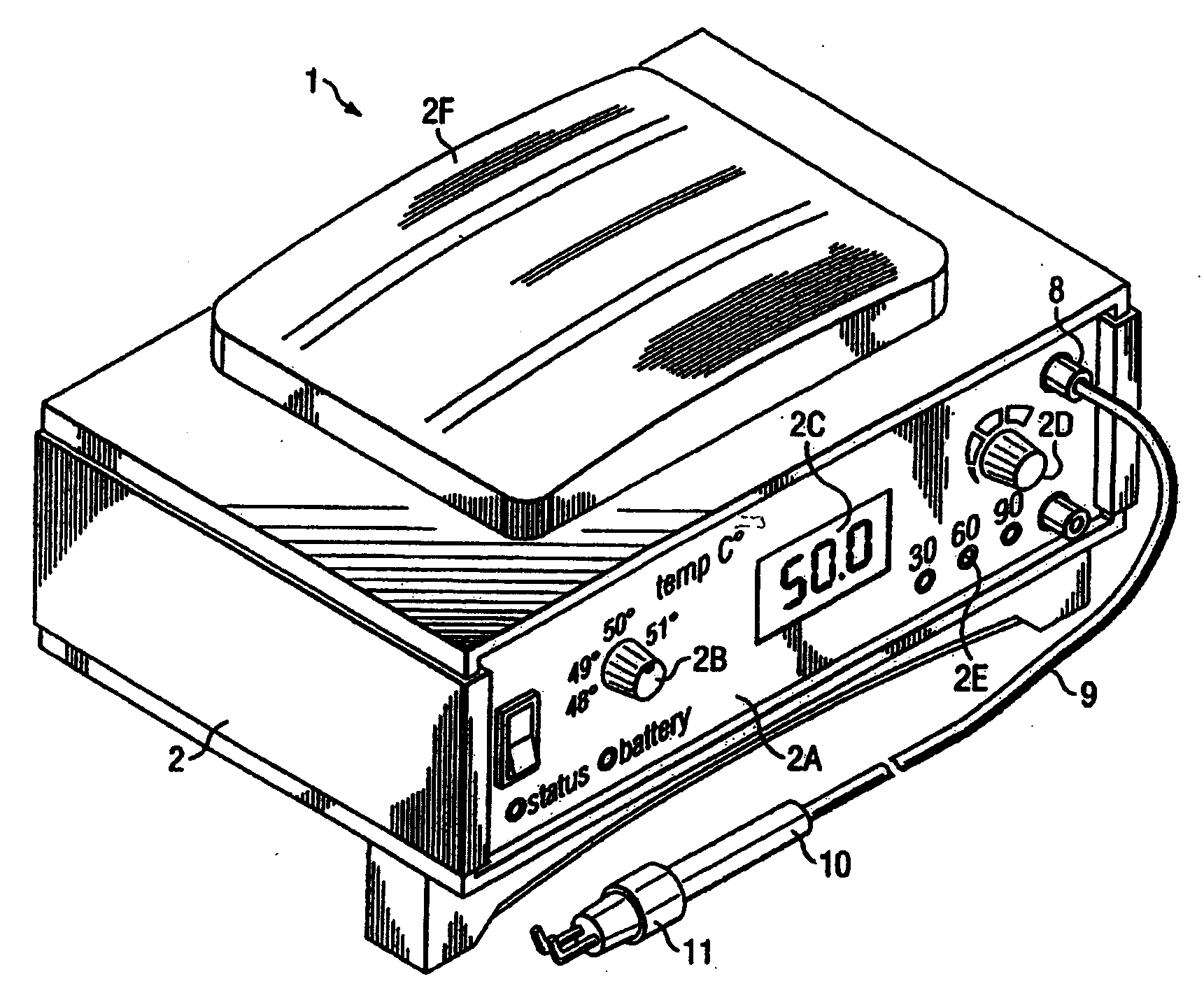
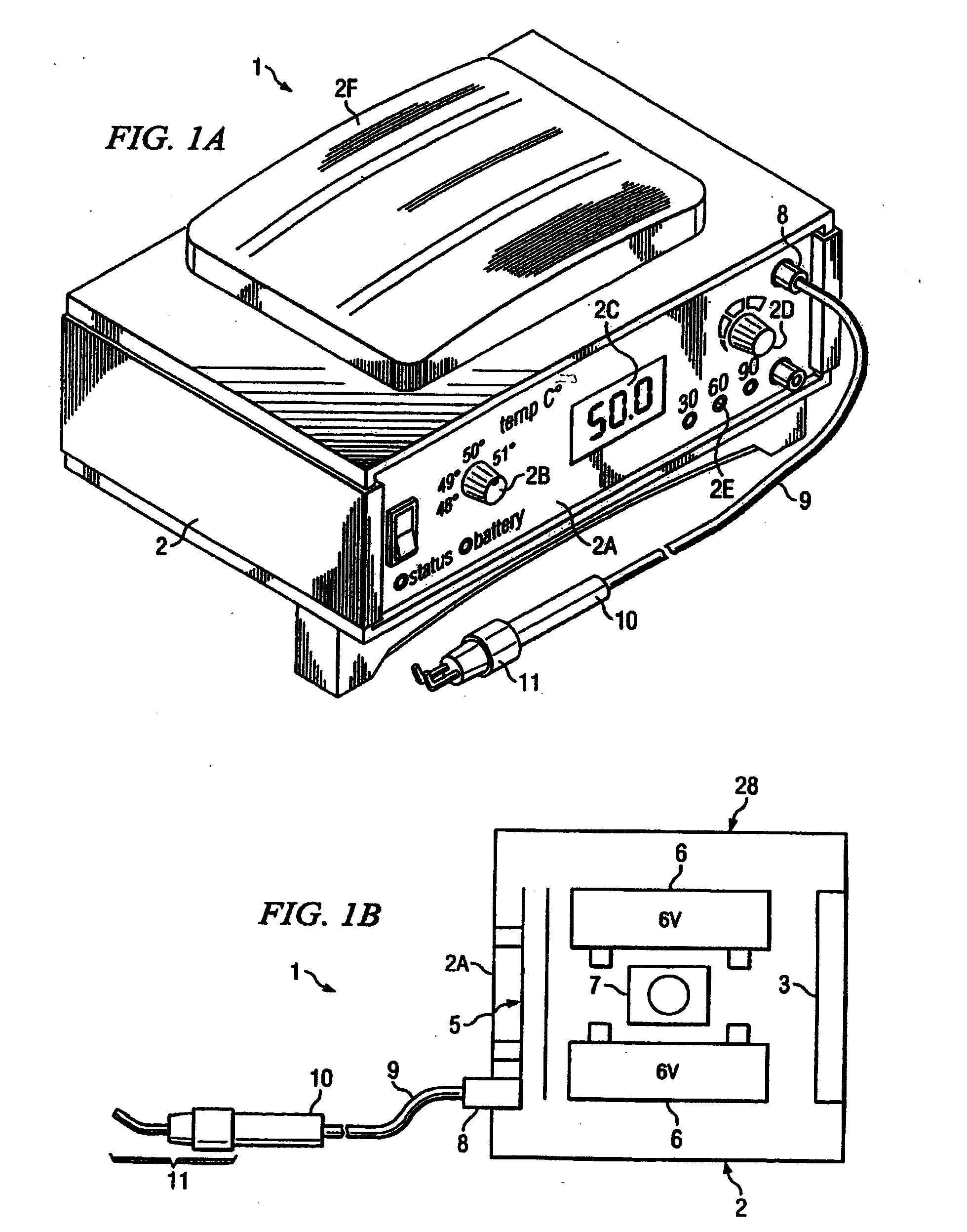
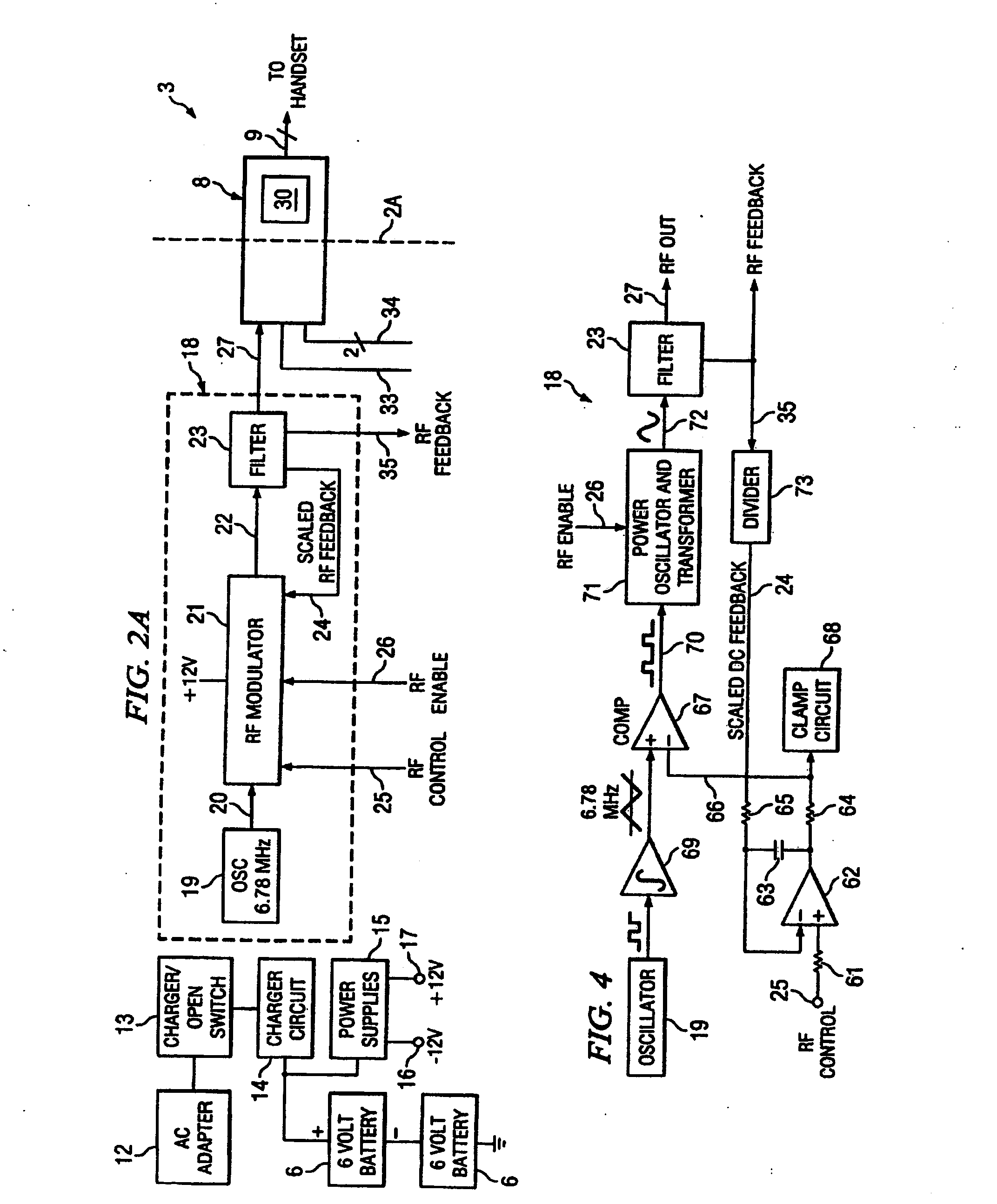
  • Hyperthermia Treatment Systems and Methods
  • Hyperthermia Treatment Systems and Methods
  • Hyperthermia Treatment Systems and Methods

Examples


Embodiment Construction

[0002]1. Field of the Invention

[0003]The present invention relates to medical systems and methods, and, more particularly, to hyperthermia treatment systems and methods.

[0004]2. Background of the Invention

[0005]Hyperthermia treatment systems and methods are well known for treating abnormal tissue. For example, it is well known to use such systems to apply high frequency current from a probe through the tissue under treatment to another probe, which causes the temperature of the tissue to rise to a selected level high enough to kill abnormal tissue, without permanently damaging adjacent healthy tissue.

[0006]Use of hyperthermia treatment systems and methods to noninvasively or minimally-invasively treat abnormal or malignant tissue has increased significantly in recent years. Regarding hyperthermia treatment systems and methods, studies have shown that for a specific biological effect, there is an inverse relationship between the exposure time of the treatment and the treatment temper...


PUM


Abstract

Systems and methods are disclosed to control the temperature of an RF hyperthermia system with minimum overshoot and to improve safety by, among other things, detecting a defective temperature sensor. Temperature overshoot may be minimized by compensating for the short-term temperature difference between the area being treated and the applicator delivering the RF energy. The RF energy may heat the tissue and then the tissue may transfer heat to the applicator sensor. The system may also adapt to various applicator sizes and shapes by modifying control loop coefficients based on initial probe response.

Description

CROSS REFERENCE TO RELATED APPLICATION[0001]This application is related to, claims priority from and incorporates herein by reference co-pending U.S. provisional application Ser. No. 60 / 455,022, filed Mar. 14, 2003, entitled “HYPERTHERMIA TREATMENT SYSTEM WITH TEMPERATURE CONTROL ALGORITHM AND METHOD” by Paul C. Mioduski, Roger W. Cover and Jerry F. Rosato.DESCRIPTION OF THE INVENTION[0002]1. Field of the Invention[0003]The present invention relates to medical systems and methods, and, more particularly, to hyperthermia treatment systems and methods.[0004]2. Background of the Invention[0005]Hyperthermia treatment systems and methods are well known for treating abnormal tissue. For example, it is well known to use such systems to apply high frequency current from a probe through the tissue under treatment to another probe, which causes the temperature of the tissue to rise to a selected level high enough to kill abnormal tissue, without permanently damaging adjacent healthy tissue.[0...

Claims


Application Information

Patent Timeline
Patent Type & Authority Applications(United States)
IPC IPC(8): A61F7/00A61B17/00A61B18/00A61B18/12
CPCA61B18/1233A61B2017/00092A61B2017/00123A61B2017/00734A61B2018/00988A61B2018/00779A61B2018/00791A61B2018/00821A61B2018/00892A61B2018/00666
Inventor MIODUSKI, PAUL C.COVER, ROGER W.ROSATO, JERRY F.
Owner THERMOSURGERY TECH
Learn More