
Raid with redundant parity

a parity and parity technology, applied in the field of parity parity parity, can solve the problems of reducing the performance of the raid array, the use of uninterruptable power supply in the raid system, and the proprietary product available from a single vendor, so as to reduce the time needed for parity information regeneration

Inactive Publication Date: 2009-04-30
HITACHI GLOBAL STORAGE TECH NETHERLANDS BV
View PDF7 Cites 48 Cited by
  • Summary
  • Abstract
  • Description
  • Claims
  • Application Information

AI Technical Summary

Benefits of technology

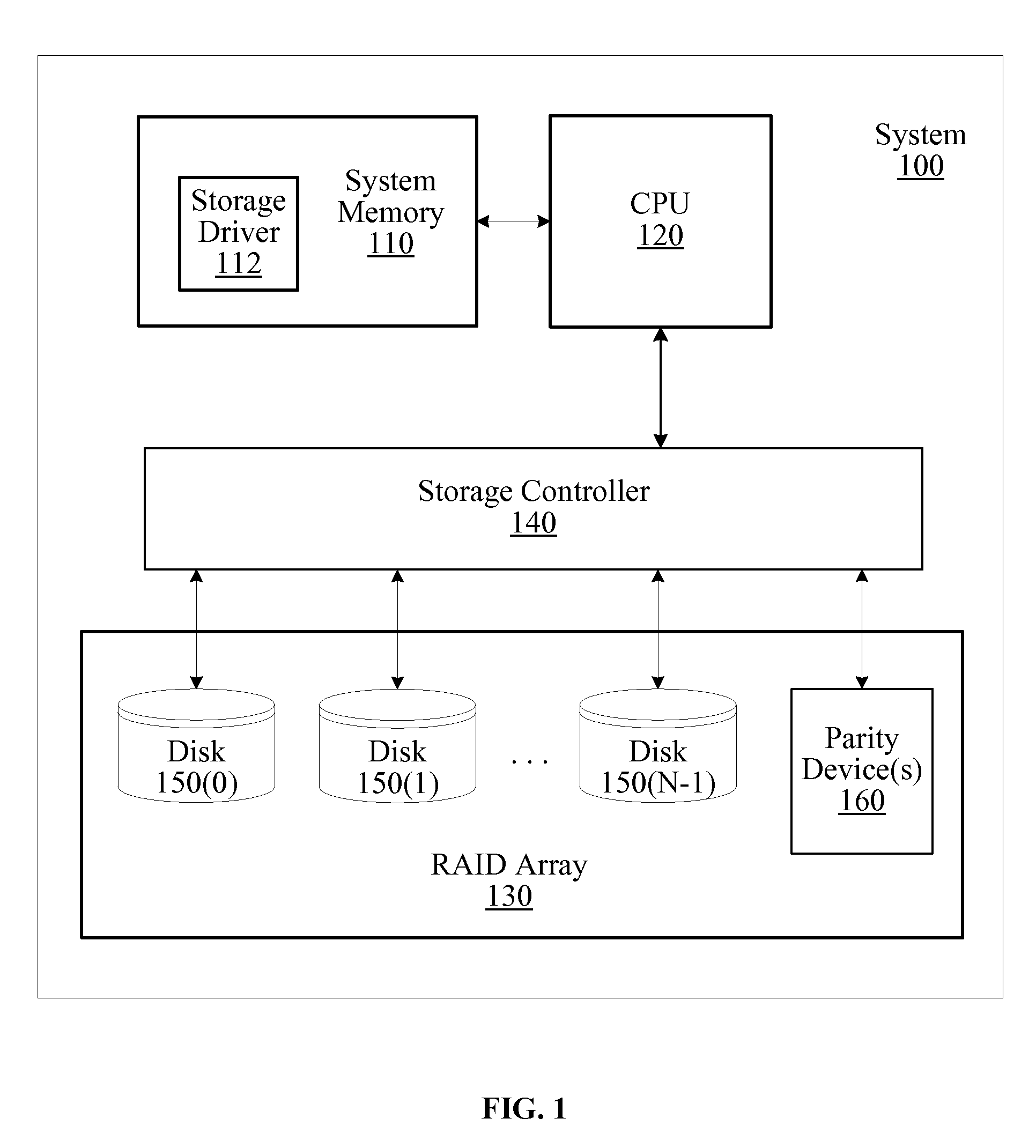
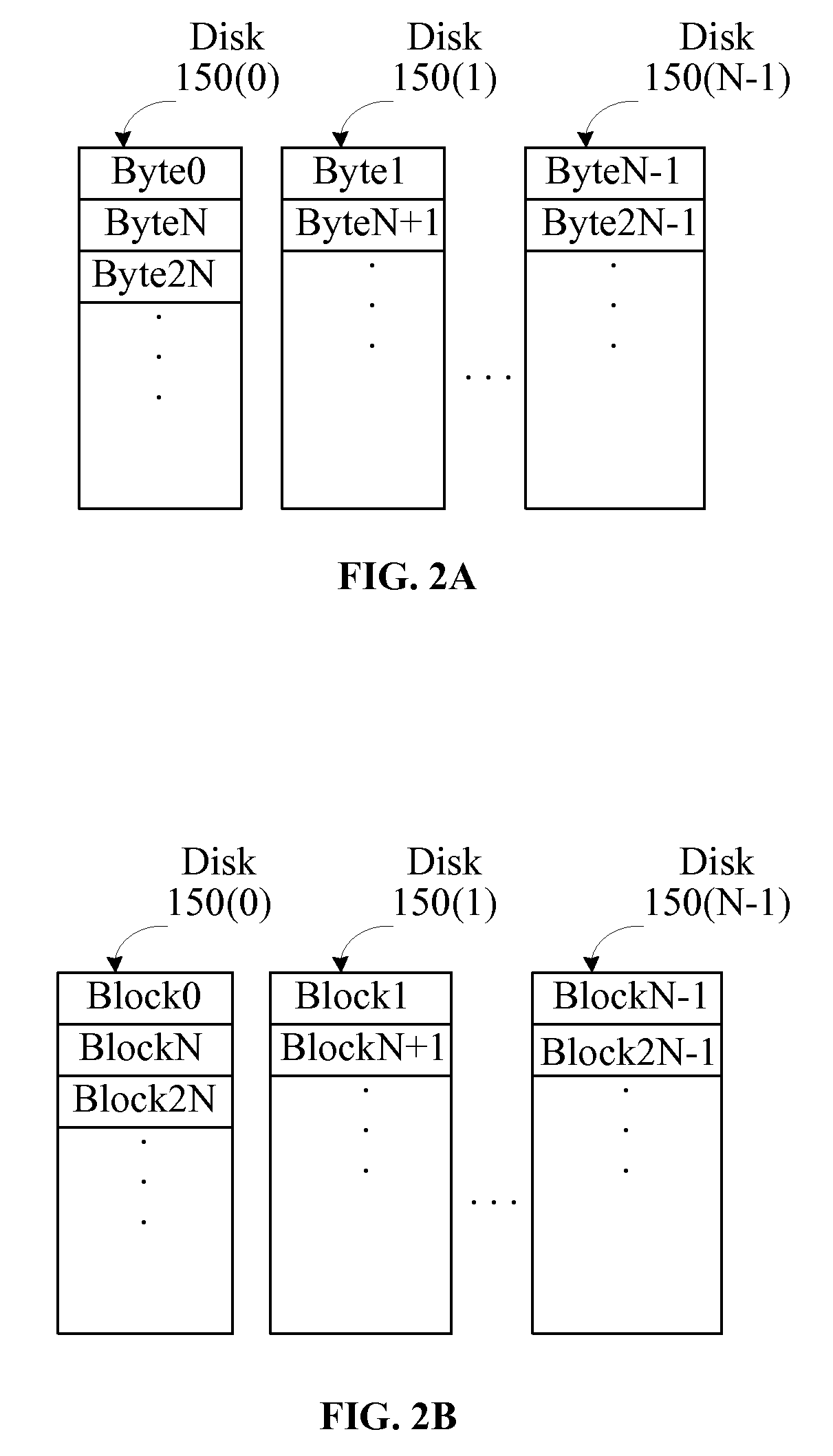
[0006]The reliability of RAID arrays configured to support RAID 3, RAID 4, and RAID 7 is improved by including redundant parity information. The parity information and / or redundant parity information may be stored using a flash storage device instead of a conventional hard disk drive. The flash storage device is available from multiple vendors and does not require an uninterruptable power supply. Dual flash storage devices are configured to store parity information in a RAID array to reduce the time needed to regenerate the parity information in the event of a dual failure compared with using conventional hard disk drives to store the parity information. A RAID 3 or RAID 4 data layout is used for data storage with additional redundant storage device(s) to provide dual parity.

Problems solved by technology

In RAID systems that store parity information on a separate parity hard disk drive, the access time needed to update the parity information may reduce the performance of the RAID array.
This solution is a proprietary product that is available from a single vendor and has a high cost.
Additionally, in order to prevent the loss of cache data during a power loss, an uninterruptable power supply must be used in the RAID system.

Method used


Image

  • Raid with redundant parity
  • Raid with redundant parity
  • Raid with redundant parity

Examples


Embodiment Construction

[0018]In the following, reference is made to embodiments of the invention. However, it should be understood that the invention is not limited to specific described embodiments. Instead, any combination of the following features and elements, whether related to different embodiments or not, is contemplated to implement and practice the invention. Furthermore, in various embodiments the invention provides numerous advantages over the prior art. However, although embodiments of the invention may achieve advantages over other possible solutions and / or over the prior art, whether or not a particular advantage is achieved by a given embodiment is not limiting of the invention. Thus, the following aspects, features, embodiments and advantages are merely illustrative and, unless explicitly present, are not considered elements or limitations of the appended claims.

[0019]FIG. 1 is a block diagram of an exemplary embodiment of a respective system 100 in accordance with one or more aspects of t...


PUM


Abstract

Methods and apparatus of the present invention include storing redundant parity information in storage devices that are configured in a RAID array. Conventional hard disk drives are configured to store data in RAID 3 or RAID 4 data layouts. A storage controller is configured to generate the parity information for the data written to the hard disk drives. One or more of the devices storing the parity information may be a flash storage device.

Description

BACKGROUND OF THE INVENTION[0001]1. Field of the Invention[0002]Embodiments of the present invention generally relate to adding additional redundancy in some Redundant Array of Independent Disks / Drives (RAID) configurations and configuring flash memory devices in a RAID to store parity information.[0003]2. Description of the Related Art[0004]Conventional RAID systems use hard disk drives to store data and parity information. In RAID systems that store parity information on a separate parity hard disk drive, the access time needed to update the parity information may reduce the performance of the RAID array. One solution to reduce the access time for the parity hard disk drive includes a cache in front of the parity hard disk drive. This solution is a proprietary product that is available from a single vendor and has a high cost. Additionally, in order to prevent the loss of cache data during a power loss, an uninterruptable power supply must be used in the RAID system.[0005]This pre...

Claims


Application Information

Patent Timeline
Patent Type & Authority Applications(United States)
IPC IPC(8): G06F11/10G06F12/00
CPCG06F11/1008G06F11/1088G06F11/108G06F11/1068
Inventor SELINGER, ROBERT D.
Owner HITACHI GLOBAL STORAGE TECH NETHERLANDS BV
Learn More