
System and method for control of power distribution

a power distribution and system technology, applied in non-electric variable control, process and machine control, instruments, etc., can solve the problems of grid splits and segments, requiring the reconfiguration of existing control devices, and the place to achieve this functionality

Active Publication Date: 2009-04-30
GENERAL ELECTRIC CO
View PDF53 Cites 75 Cited by
  • Summary
  • Abstract
  • Description
  • Claims
  • Application Information

AI Technical Summary

Benefits of technology

[0013]The above described and other features are exemplified by the following detailed description and appended claims.

Problems solved by technology

Typical systems in place to achieve this functionality are limited to simple power network topologies, typically using a maximum of two feeds, and / or a single substation, and furthermore have limitations in the number of interconnections, splits and segments identifiable and segregatable in the grid.
However, such distributed logic control systems generally require the use of the same type of control devices, often from the same supplier, across the entire distribution power grid.
Furthermore, adding control devices and / or field devices in the network may require the reconfiguration of existing control devices.
Furthermore, such systems are not capable of less than three phase restoration unless a single central controller is utilized for the entire power distribution grid.
Typical approaches thus are either centralized, or in the case of distributed implementations, are limited in the types and extents of power grid layouts that can be accounted for, due to topology constraints.
These approaches thus have restricted applicability, and generally require highly skilled engineers for configuration of control devices for non-typical grid layouts.

Method used


Image

  • System and method for control of power distribution
  • System and method for control of power distribution
  • System and method for control of power distribution

Examples


example 1

Initial Processing

[0168]A. The control application observes a fault, freezes and keeps the immediate (pre-fault time) history values intact for all arrays A(s0,f0,n). The trigger condition is determined by, for example: i) noting a loss of voltage in a node (i.e. change in Vx value), ii) substation breaker tripped and the substation auto recloser locked (see Qx and Bx for A(s,f,0)), and / or iii) reclosers in the sector tripped and locked (see Qx and Bx for A(s,f,n)). The controller and feeder representing the faulted sector is referred to as (s=s0, f=f0).

[0169]B. The trigger controller reads all nodes reporting a fault (n) and finds the maximum value(s) of “n”=n0. The check may be based on Vx, Qx, Zx, and Bx—depending on the trigger type (for example, do not look for Bx if the trigger was based on voltage loss). Node n0 is represented by a set n(s0,f0,n0) describing the identity (“ID”) of the last node before the faulted area.

[0170]C. The control application determines whether the fa...

example 2

Isolation and Restoration Process, Three-Phase

[0171]A. Instruct “OPEN ALL-PHASE” to n(s0,f0,n0), receive ACK (acknowledgement) feedback.

[0172]B. If n(s0,f0,n0) is not a branch root (R(s0,f0,n0)=0), then: OPEN ALL-PHASE for E(s0,f0,n0). Mask the nodes having types T=P,M,X when finding E (i.e. look only for the higher active node). Receive ACK feedback.

[0173]C. If n(s0,f0,n0) is a branch root (R(s0,f0,n0)0), look-up R for all downstream branch borders, then OPEN ALL-PHASE for all (s0,f0,R(n0)), receive ACK feedback from all.

[0174]D. If ACK feedback is not received and times out, the program is aborted and an appropriate alarm is raised. If all steps have been accomplished and all appropriate acknowledgements received, isolation of the faulted segment is now complete (i.e., the active nodes surrounding the faulted segment have been opened) and the control application proceeds to restore one or more of the isolated segments between the faulted segment and the edge node(s).

[0175]E. CLOSE...

example 3

Isolation and Restoration Process, Three-Phase

[0195]Initial processing may be performed as in Example 1. If the control application determines that the fault is in less than three phases, i.e. one or two phase fault, the control application proceeds as follows.

[0196]1. The control application in the trigger DAC identifies the faulted phase(s) into a data set entitled “F_PH (a,b,c)”. “a, b and c” refer respectively to each of the three phases, where a,b,c=1 for faulted phases. The identification may be accomplished by looking at the Z and Q data associated with nodes between the breaker and n0.

[0197]2. The control application builds two new arrays derived from the main array, but with two masks applied:

[0198]F_A (s,f,n)=A(s,f,n) AND{F‘3PH} AND {active node types being T=S31, S1, R31, R1}.

[0199]The F_A (s,f,n) array is the array representing the active node faulted phases, which is considered for isolation and restoration, using methods as in three-phase faults (all inputs, commands a...


PUM


Abstract

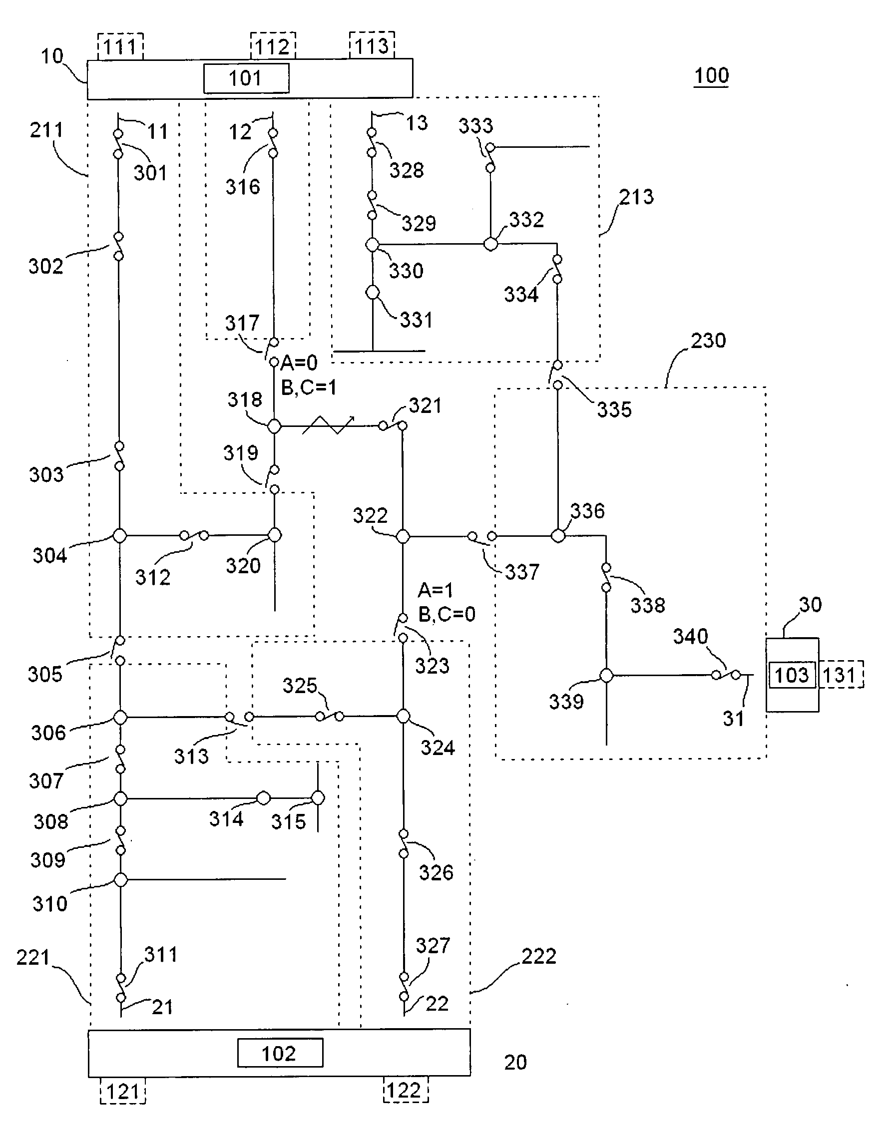
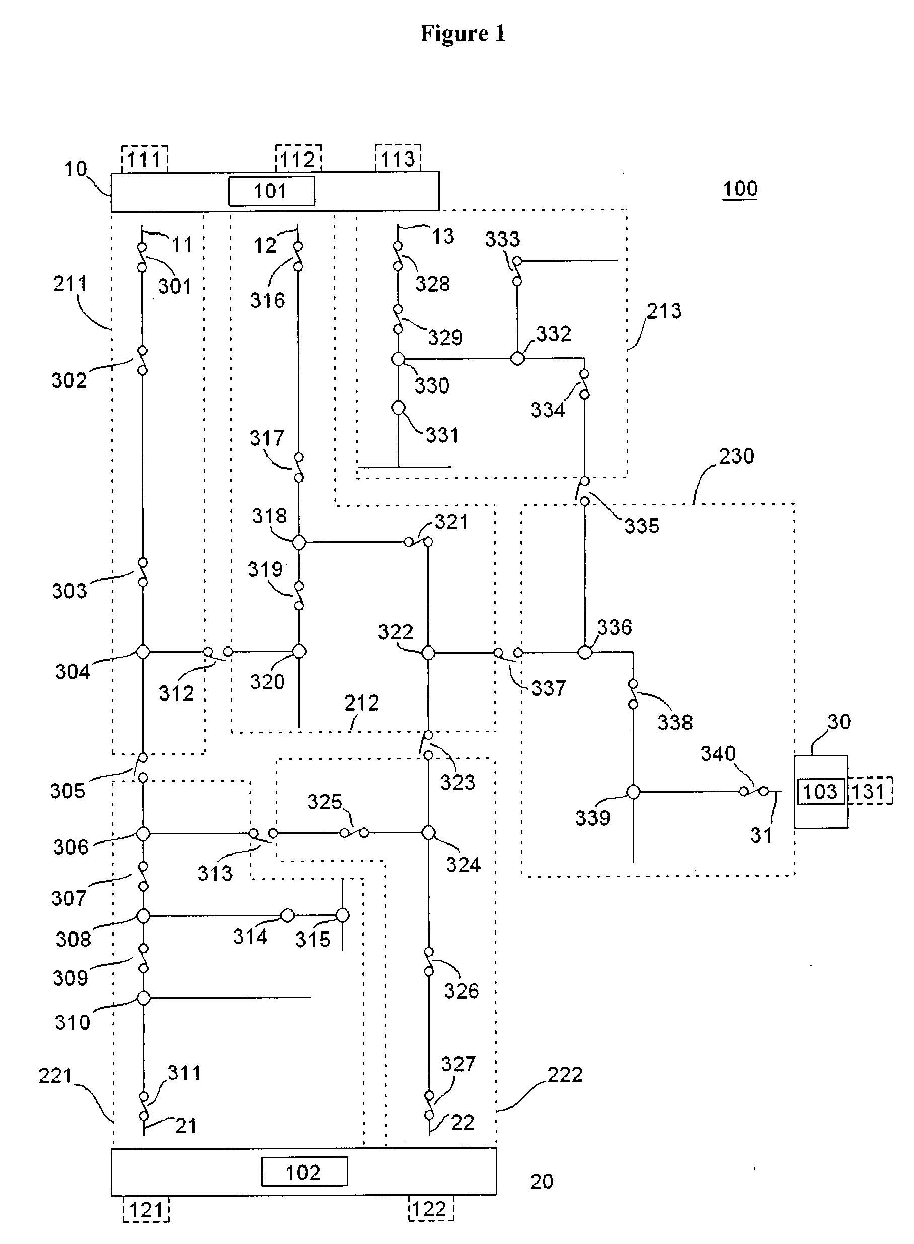
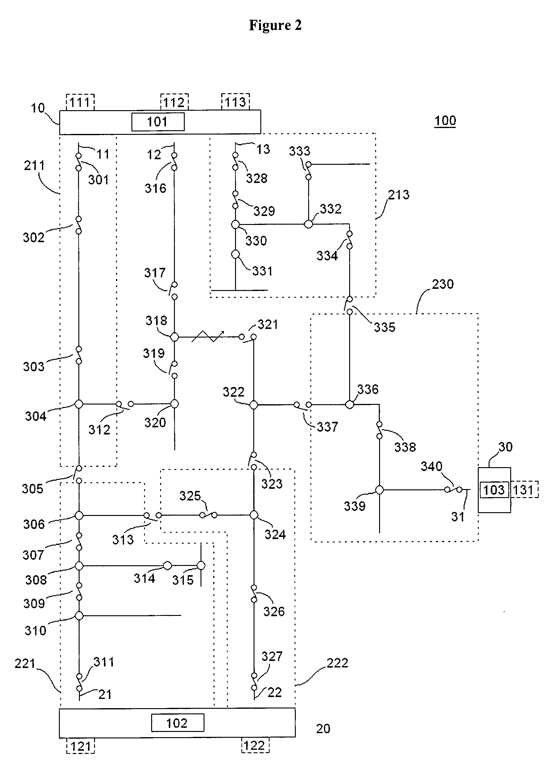
A system for controlling a multi-feed power distribution network is described herein. The network includes a first network sector that includes a first plurality of devices connected to a first power source and a second network sector that includes a second plurality of devices connected to a second power source. The system includes a first controller and a second controller. The first controller is configured to control operation of the first network sector and exchange data with the second controller. The second controller is configured to control operation of the second network sector and exchange data with the first controller. The system is modular and it can be expanded to include additional controllers as necessary. Methods and a computer program product for controlling a multi-feed power distribution network are also described.

Description

BACKGROUND OF THE INVENTION[0001]The subject matter disclosed herein relates to systems and applications for controlling power distribution networks with multiple feeds from one or more substations.[0002]Electrical power distribution networks (i.e., grids) generally consist of multiple segments tied together via switches and other field devices, and are generally fed from one or more sources. When these networks use active devices which can sense conditions in power circuits formed in the networks and can distinguish between the various segments (e.g. controlled switches, reclosers, etc.), then it is possible in the case of power faults inside a given segment of the network, on all or on individual phases, to isolate the faulted segment and thereafter restore power to the remaining segment(s).[0003]Typical systems in place to achieve this functionality are limited to simple power network topologies, typically using a maximum of two feeds, and / or a single substation, and furthermore ...

Claims


Application Information

Patent Timeline
IPC IPC(8): G06F19/00
CPCH02H7/261G06Q10/06G06Q50/06H02H1/0092H02H3/063H02H7/262H02H7/263H02H7/28H02J3/00Y04S10/12H02J3/381H02J3/0073H02J13/00017H02J13/00016H02J13/00034H02J13/0004H02J1/00Y02E40/70Y04S40/124Y02E60/00
Inventor POPESCU, BOGDAN CRISTIAN
Owner GENERAL ELECTRIC CO
Learn More