Signal processing apparatus, signal transmitting system, and signal processing method
a signal processing and signal technology, applied in the direction of digital transmission, amplitude demodulation, pulse technique, etc., can solve the problem of increasing power consumption
- Summary
- Abstract
- Description
- Claims
- Application Information
AI Technical Summary
Problems solved by technology
Method used
Image
Examples
embodiment 1
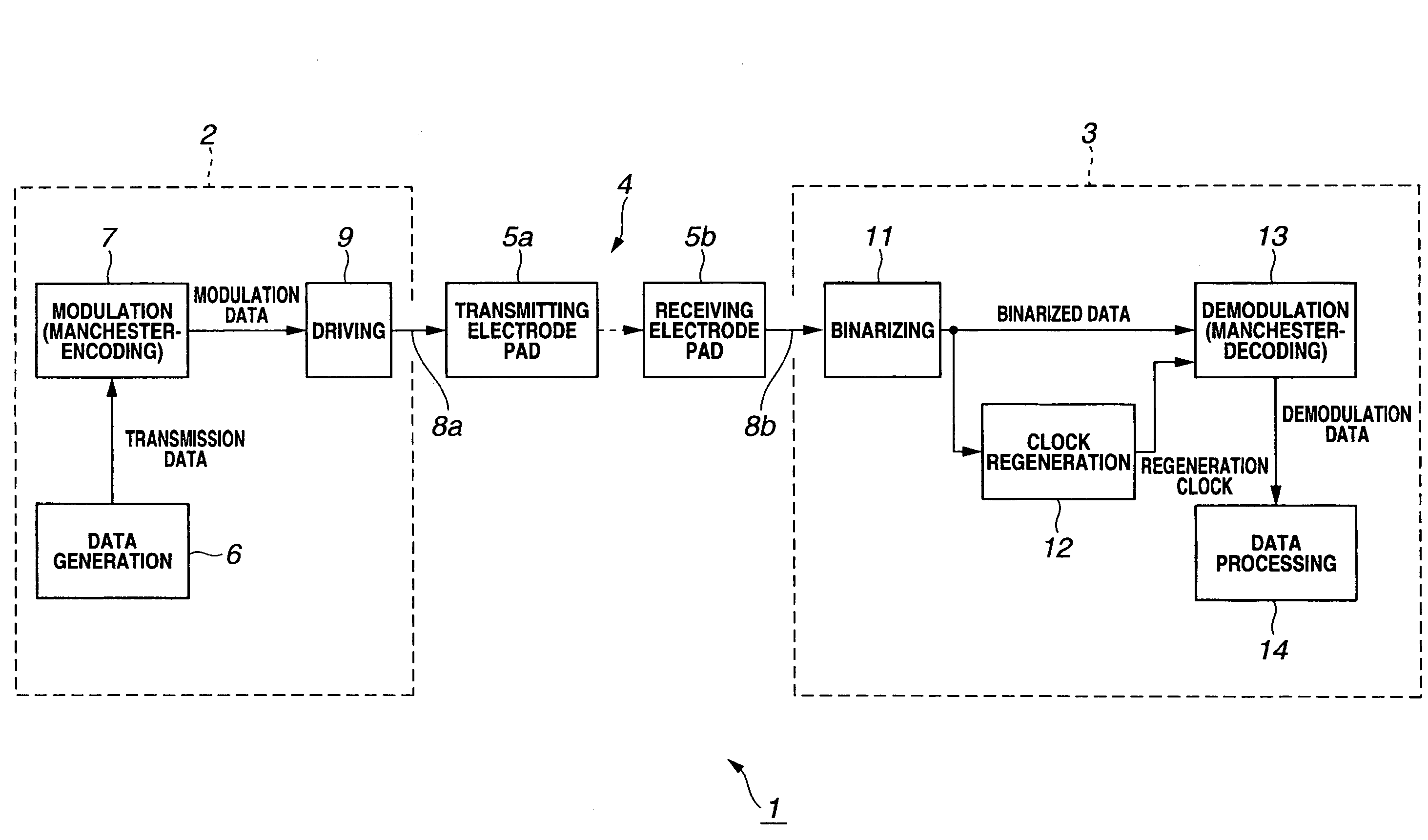
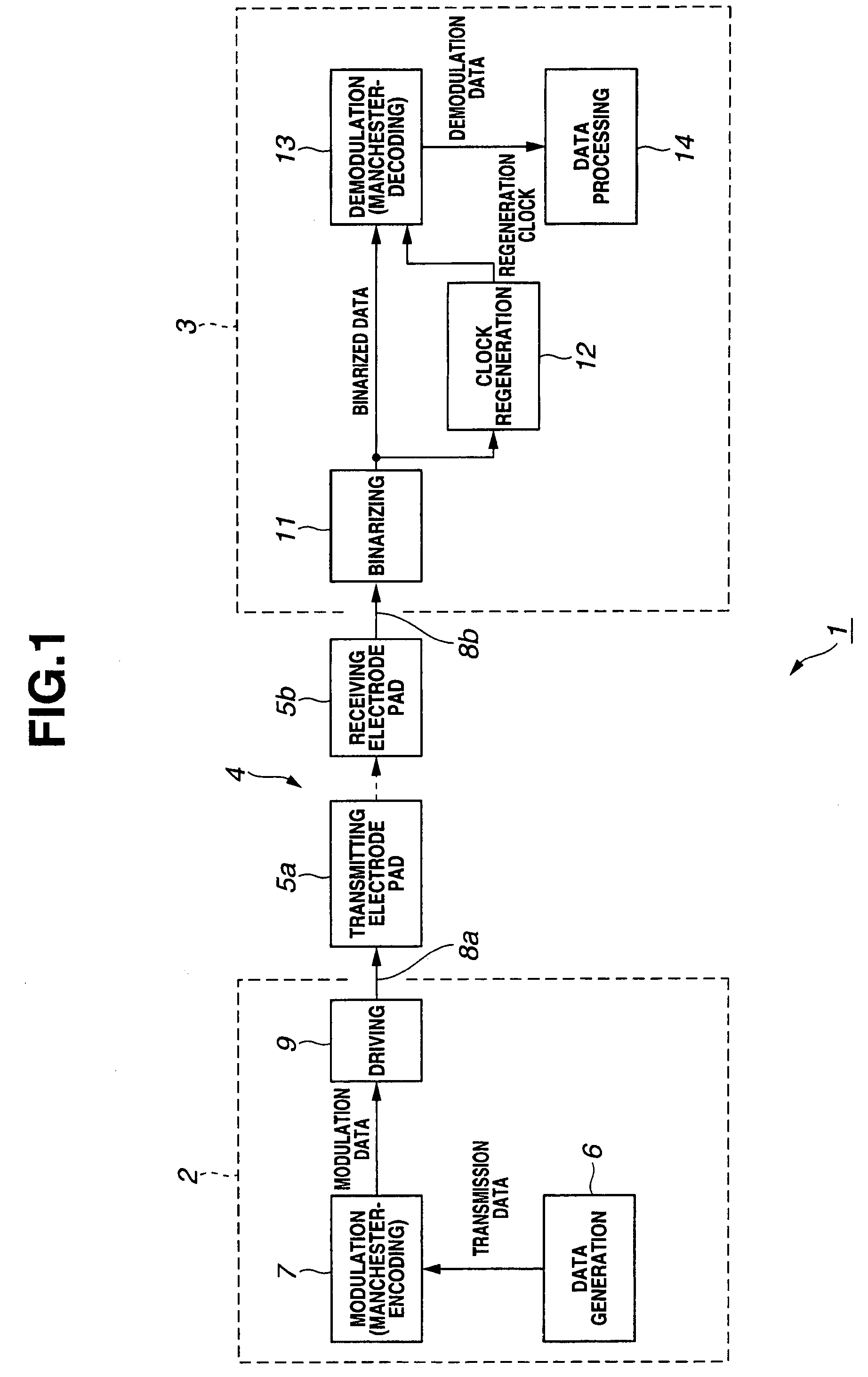
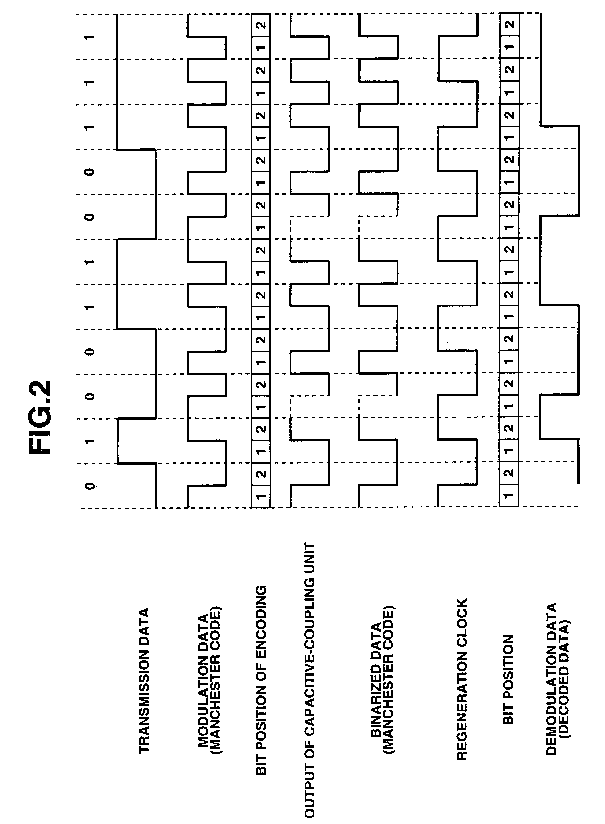
[0030]FIG. 1 to FIG. 4 relate to an embodiment 1 of the present invention, and FIG. 1 is a block diagram illustrating a configuration of a signal transmitting system provided with the embodiment 1 of the present invention, FIG. 2 is a timing diagram illustrating an operation for transmitting a signal, FIG. 3 is a flowchart for an operation content modulating data to the Manchester code, and demodulating the modulated data, and FIG. 4 is a diagram illustrating one example of the first and second bit eye patterns of the Manchester code when transmitting the Manchester code through a capacitive-coupling unit.
[0031]A first object of the present embodiment is to provide a signal processing apparatus and a signal processing method in which the Manchester code transmitted through a capacitive-coupling unit can be demodulated at a low error rate, and with power consumption suppressed (that is, with power consumption reduced). A second object of the present embodiment is to provide the signa...
embodiment 2
[0074]FIG. 5 is a block diagram illustrating a configuration of a signal transmitting system 1B provided with an embodiment 2 of the present invention. An object of the present embodiment is to provide the signal processing apparatus and the signal processing method in which the Manchester code is demodulated with the power consumption suppressed.
[0075]In the signal transmitting system 1B, an optical coupling unit 16 is adopted in place of the capacitive-coupling unit 4 of the signal transmitting system 1 of FIG. 1.
[0076]The optical coupling unit 16 is provided in, for example, a terminal side of the transmitting line 8a, and includes:[0077]an optical transmitter 15a which is an electro-optical converter converting an electrical signal to an optical signal; and[0078]an optical receiver 15b which is an optical-electro converter receiving (light-receiving) the optical signal converted by the optical transmitter 15a to convert the received optical signal to the electrical signal.
[0079]...
PUM
 Abstract
Description
Claims
Application Information
 - R&D
- Intellectual Property
- Life Sciences
- Materials
- Tech Scout
- Unparalleled Data Quality
- Higher Quality Content
- 60% Fewer Hallucinations
Browse by: Latest US Patents, China's latest patents, Technical Efficacy Thesaurus, Application Domain, Technology Topic, Popular Technical Reports.
© 2025 PatSnap. All rights reserved.Legal|Privacy policy|Modern Slavery Act Transparency Statement|Sitemap|About US| Contact US: help@patsnap.com


