
Display panel with improved reflectivity

a technology of reflectivity and display panel, which is applied in the field of display panels, can solve the problems of high light reflectivity of potting material and image created by pixel elements, and achieve the effects of less ambient light reflection, accurate, precise, and no need for complex and/or laborious process steps

Inactive Publication Date: 2009-04-30
BARCO NV
View PDF5 Cites 13 Cited by
  • Summary
  • Abstract
  • Description
  • Claims
  • Application Information

AI Technical Summary

Benefits of technology

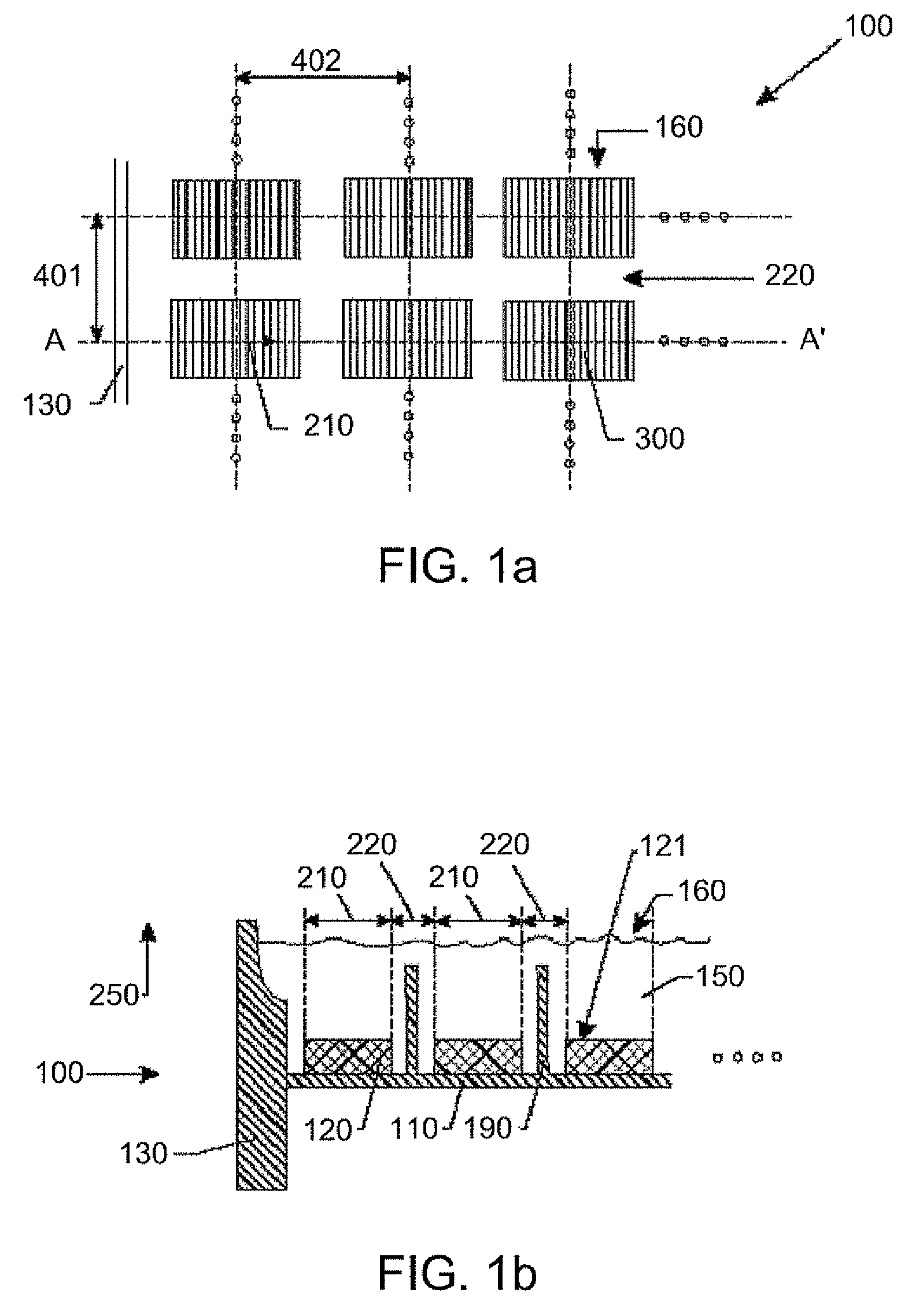
[0006]It is an object of the present invention to provide lighting and / or display elements, e.g. good display panels or good leds, and methods of making the same, the panels optionally being for use as outdoor display panels or parts of outdoor displays. An advantage of panels according to embodiments of the present invention is that they can show less reflection of ambient light, hence allow to display images more clear under different angles of incident ambient light, even for images having a low intensity difference between adjacent pixels. Embodiments of the present invention can also provide a method for manufacturing display panels having these advantages. Such methods advantageously can be accurate, precise and without the need of complex and / or labor intensive process steps.

Problems solved by technology

A disadvantage however is that the higher the light transparency of the potting material, the higher the light reflectivity of the potting material, e.g. the reflectivity for the ambient light, e.g. solar light, at its surface.
Due to this reflection, the image created by the pixel elements may become disturbed, i.e. unclear.

Method used


Image

  • Display panel with improved reflectivity
  • Display panel with improved reflectivity
  • Display panel with improved reflectivity

Examples


Embodiment Construction

[0117]The present invention will be described with respect to particular embodiments and with reference to certain drawings but the invention is not limited thereto but only by the claims. The drawings described are only schematic and are non-limiting. In the drawings, the size of some of the elements may be exaggerated and not drawn on scale for illustrative purposes. The dimensions and the relative dimensions do not correspond to actual reductions to practice of the invention.

[0118]Furthermore, the terms first, second, third and the like in the description and in the claims, are used for distinguishing between similar elements and not necessarily for describing a sequence, either temporally, spatially, in ranking or in any other manner. It is to be understood that the terms so used are interchangeable under appropriate circumstances and that the embodiments of the invention described herein are capable of operation in other sequences than described or illustrated herein.

[0119]More...


PUM


Abstract

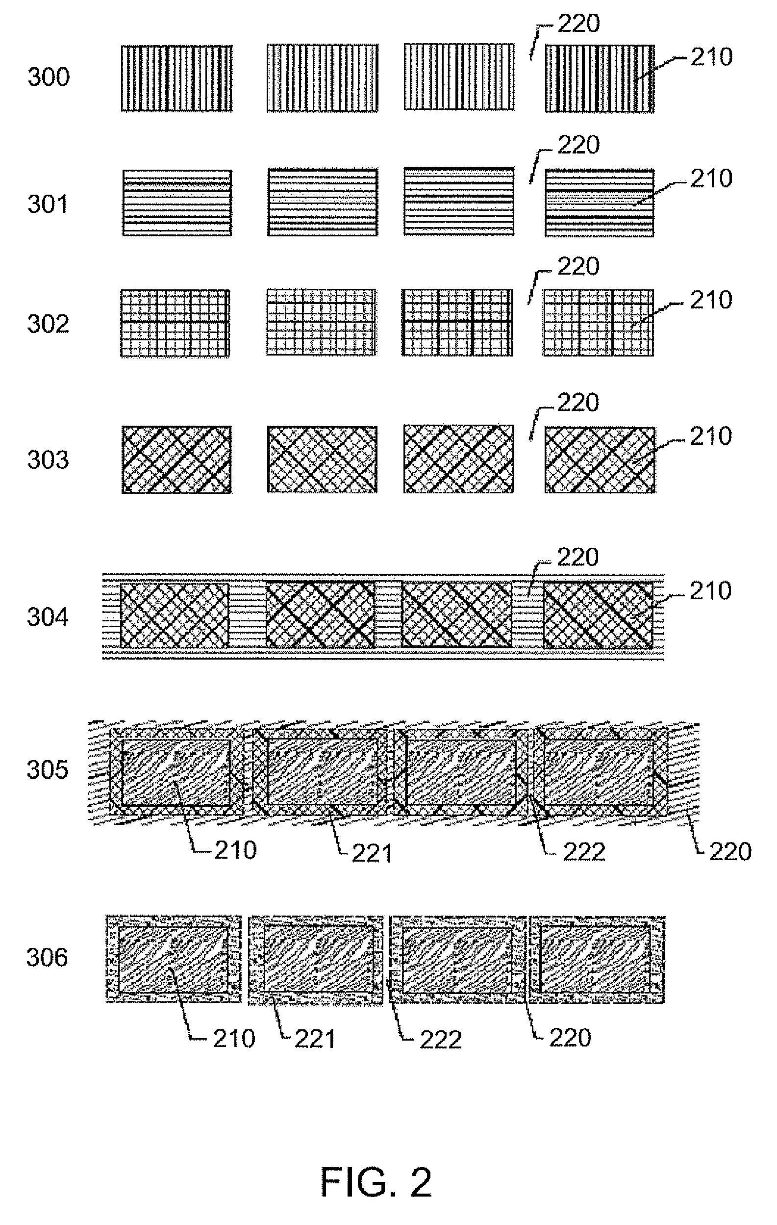
A display or lighting element comprising at least one pixel element for producing or controlling light is provided. The pixel element has a light emitting surface. The display or lighting element furthermore includes a substantially transparent material above at least the light emitting surface. The substantially transparent material above the light emitting surface has a modified roughness so as to decrease the reflectivity of the substantially transparent material above the light emitting surface.

Description

[0001]This application is a continuation-in-part of application Ser. No. 12 / 216,643 filed on Jul. 9, 2008, the entirety of which is incorporated herein by reference.TECHNICAL FIELD OF THE INVENTION[0002]The present invention relates to display panels, such as fixed format display panels, e.g. EL panels, Plasma panels, OLED panels, LED panels or LCD panels and to a method to provide a lighting device or display panel, such as EL panels, OLED panels, Plasma panels, LED panels or LCD panels.BACKGROUND OF THE INVENTION[0003]Fixed format display panels known in the art usually comprise an array of pixel elements for producing or controlling light over a small area, such as e.g. LED elements, OLED elements, inorganic EL-pixel elements, LCD's, E-ink or any other suitable pixel element as used in LED-displays, OLED displays, LCD displays, plasma displays, field emission displays, EL-displays, digital mirror devices, LCOS devices, lighting devices and alike. The pixel elements may be reflect...

Claims


Application Information

Patent Timeline
IPC IPC(8): B29D11/00G02B5/00
CPCH01L51/5237H01L51/5281H01L51/5275H10K59/87H10K59/871H10K59/879H10K59/8791H10K50/86H10K50/84H10K50/841H10K50/858
Inventor DEVOS, BRUNONOYELLE, KATRIENGERETS, PETER
Owner BARCO NV
Learn More