
Media storing and feeding device with maximum angular speed of reels reduced

a technology of storing and feeding devices, which is applied in the direction of transportation and packaging, thin material processing, article delivery, etc., can solve the problems of increasing not allowing the tapes to be loosened, and the greater the angular speed the shorter the lifetime, so as to reduce the number of one-way clutches, reduce the maximum angular speed, and prolong the lifetime of torque limiters

Active Publication Date: 2009-04-30
OKI ELECTRIC IND CO LTD
View PDF10 Cites 23 Cited by
  • Summary
  • Abstract
  • Description
  • Claims
  • Application Information

AI Technical Summary

Benefits of technology

The present invention provides an improved media storing and feeding device. The device includes a reel that winds up a tape, a reel shaft that rotates the reel, a torque limiter that attaches the reel to the reel shaft, and a drum that winds up the tape and a medium together. The device is configured to wind up or rewind the tape between the reel and the drum to feed or store the medium. The reel shaft is rotated at a speed faster than a speed at which the drum rewinds the tape when feeding the medium, and at a slower speed when storing the medium. The torque limiter absorbs any difference in rotational speed between the reel shaft and the reel. This results in a longer lifespan for the torque limiters and reduces the number of one-way clutches needed.

Problems solved by technology

However, in the above-described storing and feeding operations, the tensions are always applied to the tapes, which do not allow the tapes to be loosened.
In the torque limiters, there is the problem that the greater the angular speed the shorter the lifetime.
Further, the torque limiters supporting high rotational speed are expensive, so that torque limiters making an attempt to satisfy the quality and the cost are required to be used at low rotational speed.

Method used


Image

  • Media storing and feeding device with maximum angular speed of reels reduced
  • Media storing and feeding device with maximum angular speed of reels reduced
  • Media storing and feeding device with maximum angular speed of reels reduced

Examples


Embodiment Construction

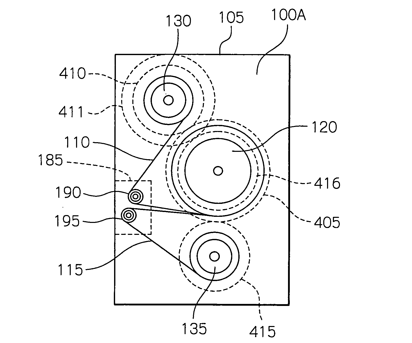
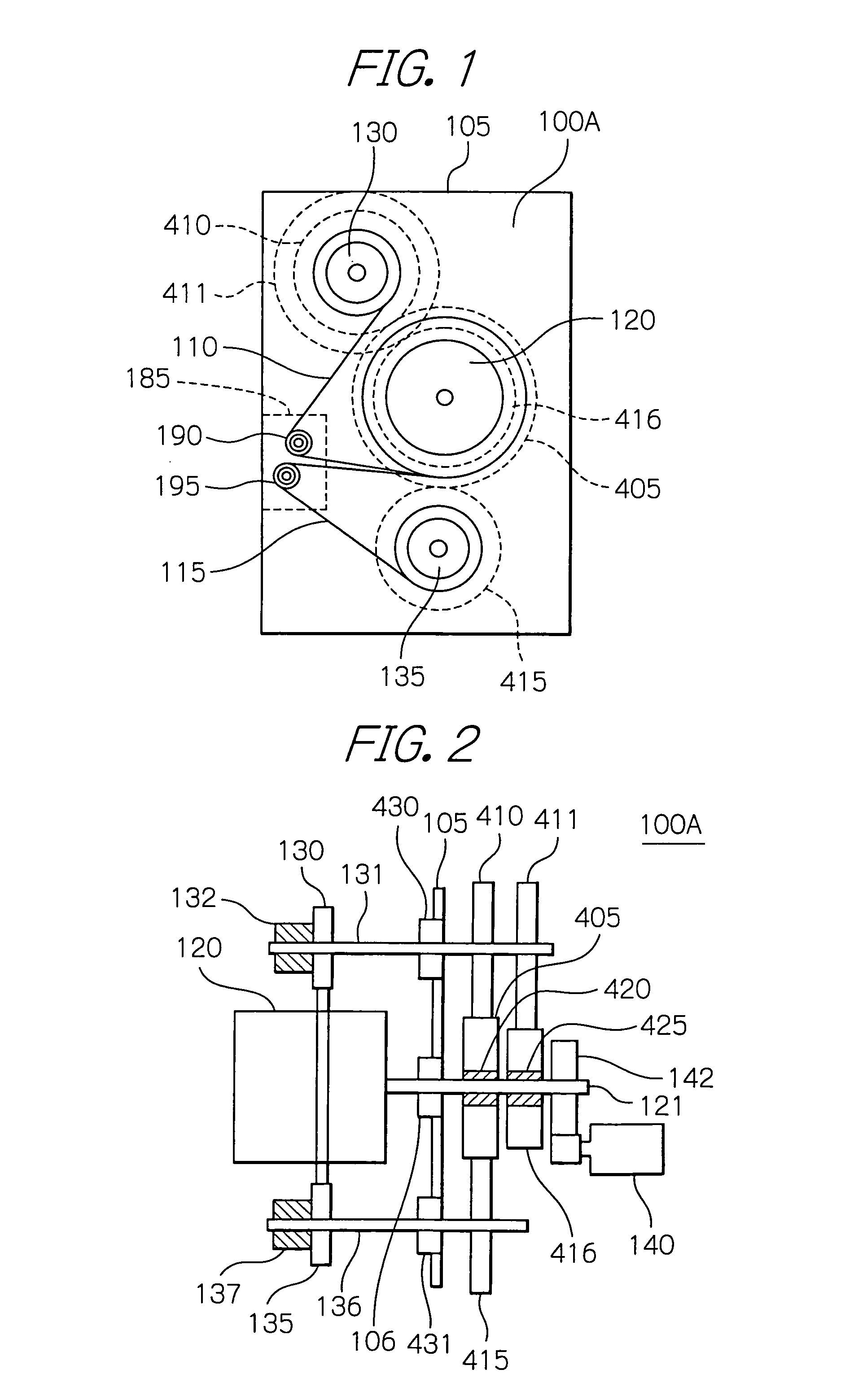
[0065]Preferred embodiments according to the present invention will be described with reference to the drawings. Reference is first made to FIGS. 1 and 2, which explanatorily show in a side and a plan view, respectively, the main part of an illustrative embodiment of a media storing and feeding device 100A in accordance with the present invention. In the following description, like portions and components will be designated with the same reference numerals even as to those of the prior art devices described above.

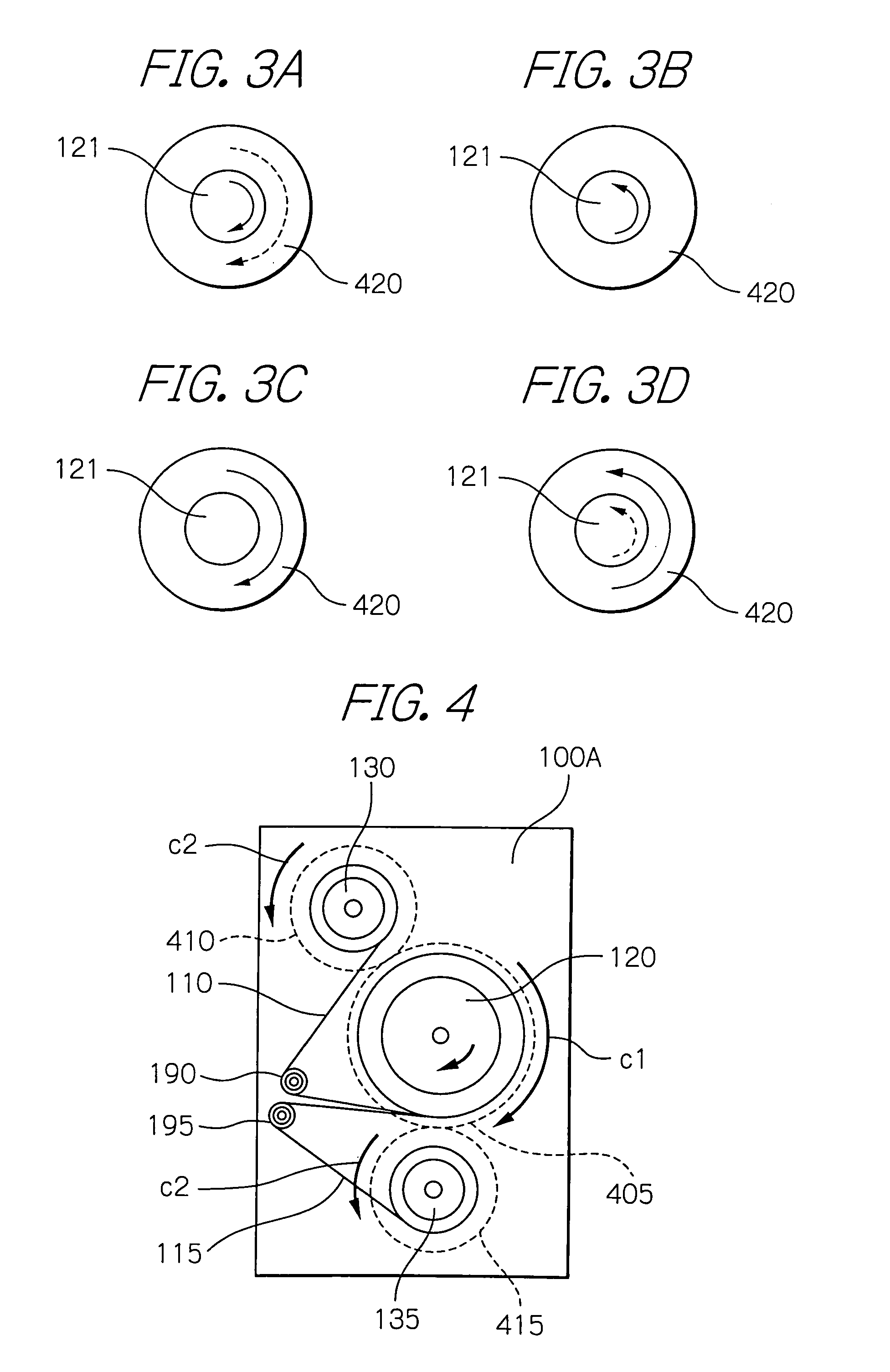
[0066]The media storing and feeding device 100A shown in the figures includes a drum gear 405, which is connected to a drum shaft 121 via a one-way clutch 420. The drum gear 405 has teeth ZA2 which are the same in number as the drum gear 150, FIG. 30. The device 100A also included reel gears 410 and 415 which are engaged with the drum gear 405, and are respectively fixed to the reel shafts 131 and 136. The reel gears 410 and 415 have respective teeth, of which the number ZA...


PUM

PropertyMeasurementUnit
speedaaaaaaaaaa
rotational speedaaaaaaaaaa
lengthaaaaaaaaaa

Abstract

In a media storing and feeding device for winding up or rewinding the tapes between reels attached to reel shafts and a drum 120 by torque limiters to feed or store the medium, at the time of feeding the medium, the reel shafts are rotated at a speed faster than a speed at which the drum rewinds the tapes, and at the time of storing the medium, the reel shafts are rotated at a speed slower than a speed at which the drum winds up the tapes. A difference between the rotational speeds of the reel shafts and the reels is absorbed by the torque limiters. The media storing and feeding device is thus implemented by inexpensive torque limiters which operate at low speed in place of expensive torque limiters supporting high speed.

Description

BACKGROUND OF THE INVENTION[0001]1. Field of the Invention[0002]The present invention relates to a media storing and feeding device, and more specifically to a device that stores and feeds leaf-like media such as bank bills, checks, deeds or instruments by winding up and rewinding a tape or tapes between a drum and reels for use in a bill depositing and withdrawing machine, a check / deed collecting and issuing machine, a bank bill / check / deed delivery system, or the like.[0003]2. Description of the Background Art[0004]Conventionally, as devices that store and feed leaf-like media by winding up and rewinding a tape or tapes between a drum and reels, there are a type of system using two tapes, as disclosed by, for example, U.S. Pat. No. 5,064,074 to Edin et al., and another type of system using a single tape as disclosed by, for example, Japanese Patent Laid-Open Publication No. 12558 / 1983. Further, as for a system to drive a tape or tapes, Edin et al., uses a plurality of motors, and, ...

Claims


Application Information

Patent Timeline
Patent Type & Authority Applications(United States)
IPC IPC(8): B65H75/00
CPCB65H29/006B65H2701/1912B65H2403/732B65H2301/41912
Inventor IWATSUKI, KEI
Owner OKI ELECTRIC IND CO LTD
Learn More