
Torque Detecting Device

Inactive Publication Date: 2009-04-30
JTEKT CORP +1
View PDF8 Cites 13 Cited by
  • Summary
  • Abstract
  • Description
  • Claims
  • Application Information

AI Technical Summary

Benefits of technology

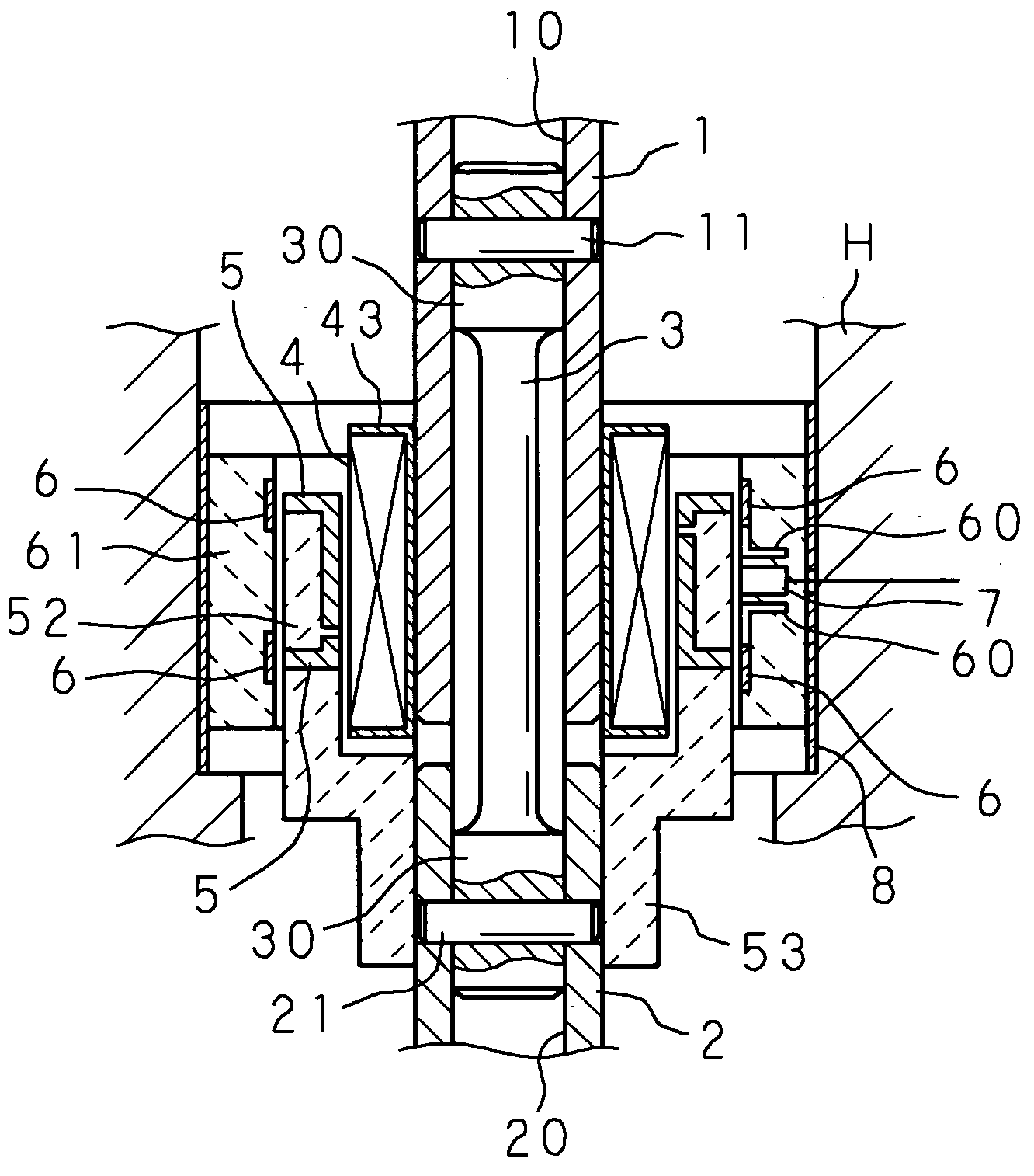
[0017]In the torque detecting device according to the first aspect of the invention, the outside of the mold member holding the magnetic flux collecting rings is covered with a simple-shaped magnetic shield having extended sections in the axial direction on both sides of the mold member. The magnetic shield is able to be mounted easily, shields directly magnetic noise from outside in the radial direction, and shields magnetic noise from both sides in the axial direction by concentrating the magnetic noise on the end faces of the extended sections on both sides. It is thus possible to eliminate the influence of magnetic noise on the magnetic flux collecting rings and achieve highly accurate detection of torque.
[0018]In the torque detecting device according to the second aspect of the invention, the magnetic shield in a cylindrical shape is externally fitted and fixed on the cylindrical mold member. Hence, it is possible to effectively shield magnetic noise by simply mounting the magnetic shield, and it is possible to achieve highly accurate detection of torque.

Problems solved by technology

In the torque detecting device constructed as described above, when magnetic noise applied from outside are superimposed on the magnetic flux collected in the magnetic flux collecting rings, the output of the magnetic sensor suffers from the influence of the noise, and there is a possibility that the accuracy of detecting the steering torque is lowered.

Method used


Image

  • Torque Detecting Device
  • Torque Detecting Device
  • Torque Detecting Device

Examples


Embodiment Construction

[0034]The following description will explain the present invention in detail with reference to the drawings illustrating a preferred embodiment thereof.

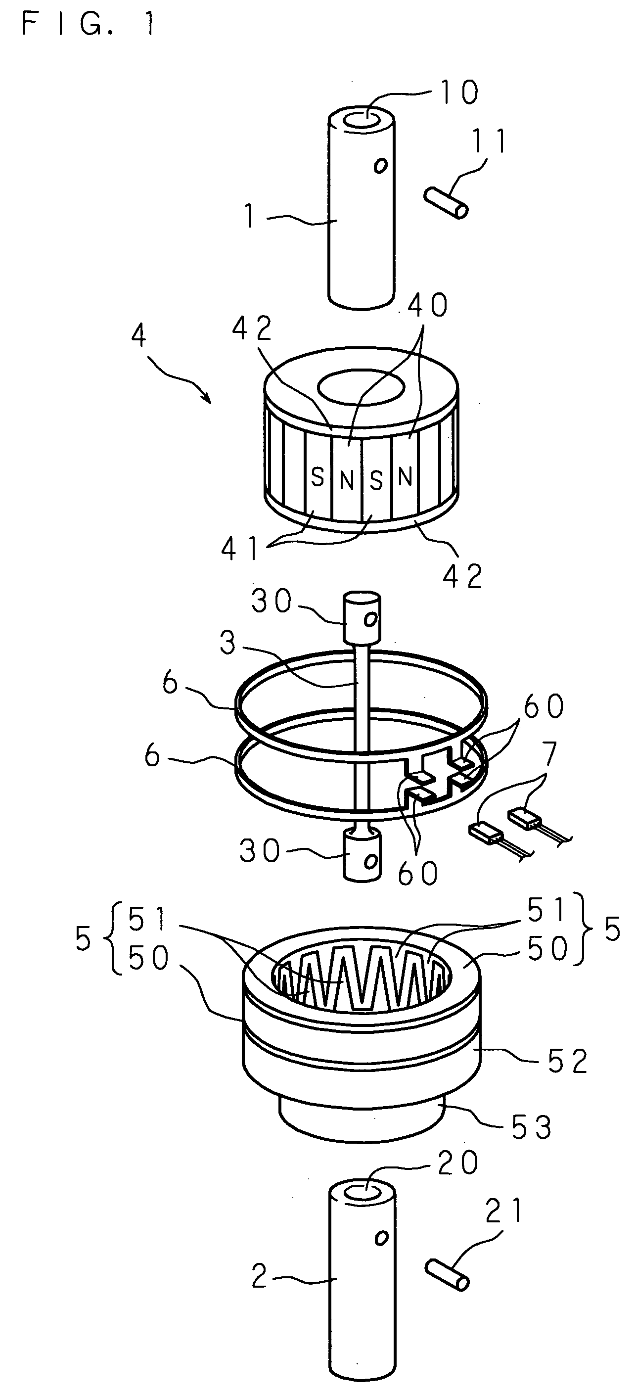
[0035]FIG. 1 is an exploded perspective view of a torque detecting device of the present invention, and FIG. 2 is a vertical cross sectional view showing an assembled state of the torque detecting device of the present invention.

[0036]The torque detecting device of the present invention aims to detect torque applied to two shafts (the first shaft 1 and second shaft 2) connected coaxially to each other through a torsion bar 3, and comprises a cylindrical magnet 4 which rotates together with the first shaft 1 and a pair of yoke rings 5 and 5 which rotate together with the second shaft 2. The torque detecting device also comprises magnetic flux collecting rings 6 and 6, which are placed closely to surround the outside of the yoke rings 5 and 5 separately, for collecting magnetic flux generated in the respective yoke rings 5 and 5, and t...


PUM


Abstract

A magnetic shield made of magnetic material in the shape of a thin cylinder is externally fitted and fixed on a cylindrical mold member holding magnetic flux collecting rings so that it has extended sections with appropriate length on both sides in the axial direction, and therefore magnetic noise from outside in the radial direction is shielded directly by the outer surface of the magnetic shield, magnetic noise from both sides in the axial direction is shielded by concentrating the magnetic noise on the end faces of the magnetic shield, and the influence on the magnetic flux collecting rings held in the mold member is eliminated.

Description

TECHNICAL FIELD[0001]The present invention relates to a torque detecting device for detecting rotational torque applied to a rotary shaft, and more particularly relates to a torque detecting device that can be suitably used to detect steering torque in an electric power steering apparatus.BACKGROUND ART[0002]In an electric power steering apparatus which assists steering by driving a steering assist motor according to the rotation operation of a steering member, such as a steering wheel, and applying rotational force of the motor to a steering mechanism, it is necessary to detect the steering torque applied to the steering member for use in the drive control of the steering assist motor. For this detection, in the prior art, the electric power steering apparatus uses a torque detecting device which is mounted in the middle of a steering shaft connecting the steering member and the steering mechanism together.[0003]In this torque detecting device, the steering shaft (rotary shaft), wh...

Claims


Application Information

Patent Timeline
IPC IPC(8): G01L3/10
CPCB62D6/10G01L5/221G01L3/104
Inventor ISHIHARA, TOSHIHARUTSUJIMOTO, TAISUKENAKANE, NAOKI
Owner JTEKT CORP
Learn More