Hair Dryer and Vacuum Device

a vacuum device and hair dryer technology, applied in the direction of curling-tongs, drying machines with progressive movements, ornamental textile articles, etc., can solve the problems of pain in the back and frustration

Inactive Publication Date: 2009-04-30
BROWN CARTER PAULINE
View PDF98 Cites 7 Cited by
  • Summary
  • Abstract
  • Description
  • Claims
  • Application Information

AI Technical Summary

Problems solved by technology

A natural consequence and inconvenience following the cutting of hair is collecting it for disposal.
Unfort...

Method used


Image

  • Hair Dryer and Vacuum Device
  • Hair Dryer and Vacuum Device
  • Hair Dryer and Vacuum Device

Examples


Embodiment Construction

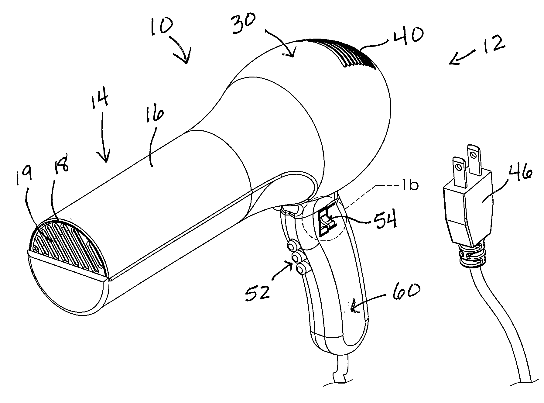
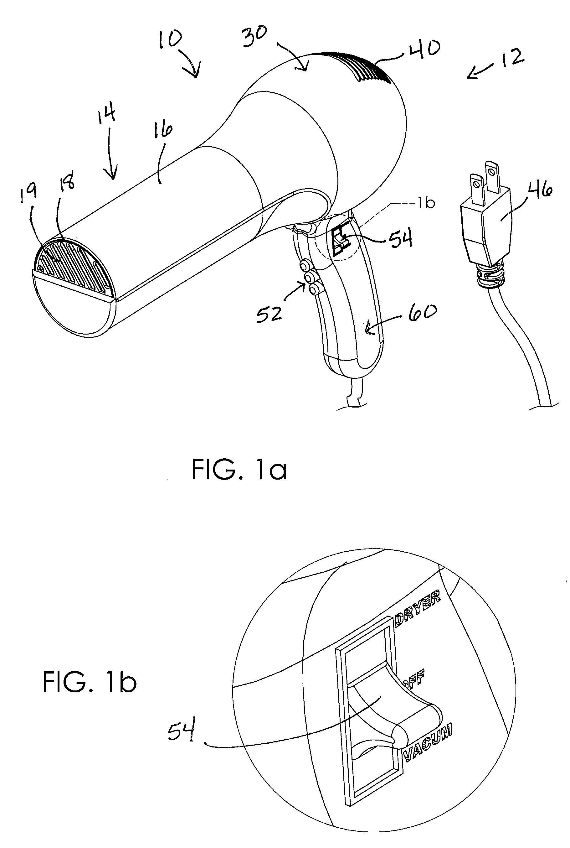
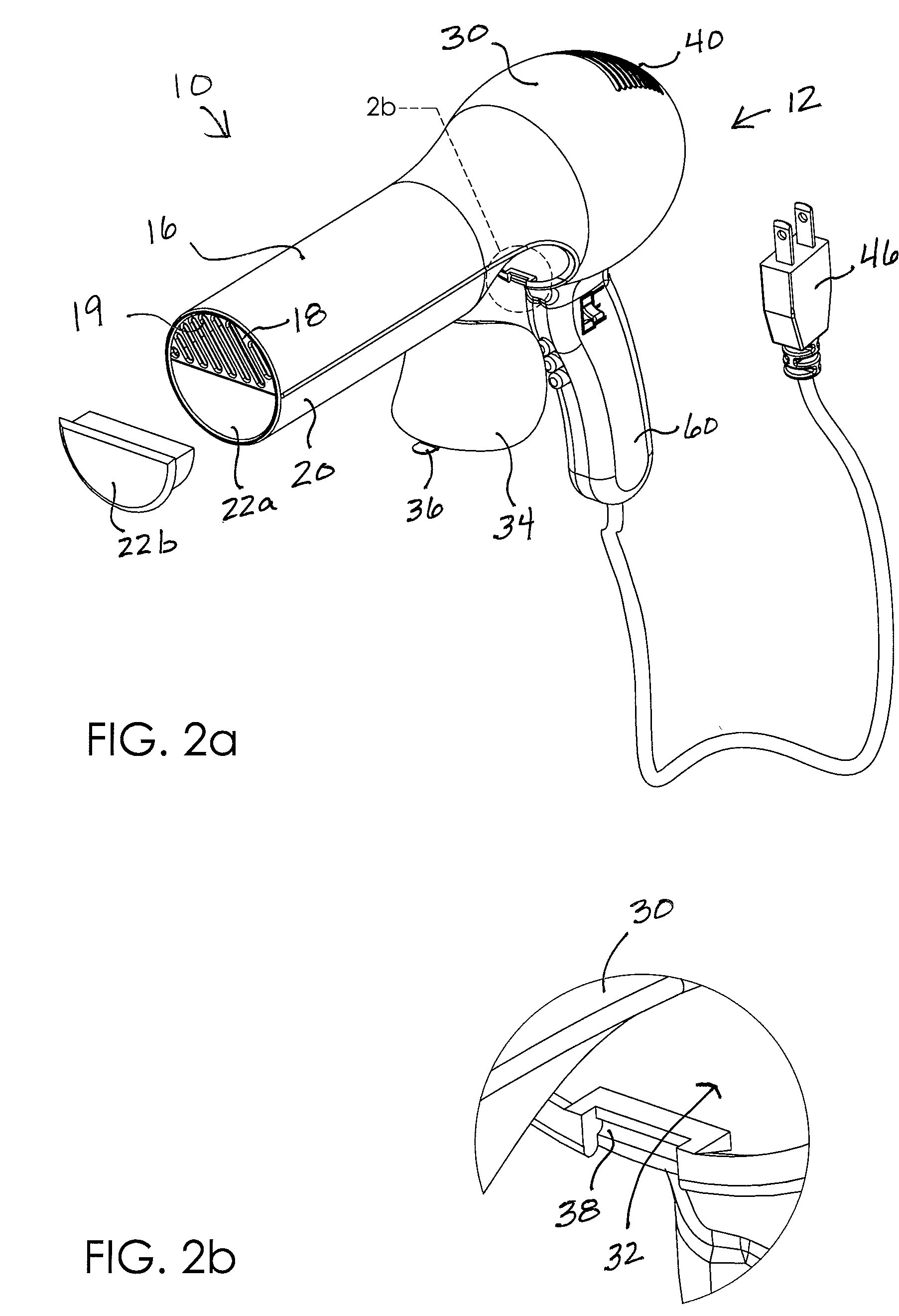
[0017]A hair dryer and vacuum device according to a preferred embodiment of the present invention will now be described with reference to FIGS. 1a to 7 of the accompanying drawings.

[0018]More particularly, the hair dryer and vacuum device 10 includes a housing 12 having a nozzle 14, a handle 60, and a body portion 30 situated between the handle 60 and nozzle 14 (FIG. 1a). The device 10 presents an overall configuration that is similar to that of a traditional blow dryer but with several unique structures and functions as will be further described below. It is understood that the nozzle 14 and body portion 30 define generally hollow interior areas.

[0019]The nozzle 14 includes a first channel 16 extending from body portion 30 to a distal end defining an outlet port 18 (FIG. 5). The nozzle 14 also includes a second channel 20 extending generally from the body portion 30 to a distal end defining an inlet port 22. The inlet 22 and outlet 18 ports are adjacent one another and, more partic...


PUM


Abstract

A hair dryer and vacuum device includes a housing having a nozzle, a handle, and a body portion situated between the handle and nozzle, the nozzle including a first channel extending from the body portion to an outlet port and a second channel extending from the body portion to an inlet port. A heating coil is mounted in the body portion for heating air and a dryer fan is positioned adjacent the heating coil that is configured to blow the heated air through the outlet port when energized. A vacuum fan is mounted in the second channel and configured to draw air into the second channel through the inlet port when energized. The device includes a collection chamber situated between the vacuum fan and the body portion and in communication with the second channel such that fallen hair is collected therein.

Description

CROSS REFERENCE TO RELATED APPLICATIONS[0001]This application is a continuation-in-part application that claims the benefit of U.S. application Ser. No. 11 / 346,433 filed Dec. 19, 2006 and titled Penny's Portable Compact Hair Dry / Vacuum.BACKGROUND OF THE INVENTION[0002]This invention relates generally to a hair care accessory and, more particularly, to a hair dryer having a vacuum suction assembly for selectively collecting fallen hair.[0003]Hot air blowing devices are commonly used by beauticians and barbers in the process of cutting and styling a person's hair. A natural consequence and inconvenience following the cutting of hair is collecting it for disposal. Picking up fallen hair typically requires the use of a broom and dust pan and then stooping over to pick up the dust pan to dump it in a trash receptacle. Unfortunately, the act of repetitively stooping to pick up collected hair may be painful back soreness and frustration.[0004]Therefore, it would be desirable to have a hair...

Claims


Application Information

Patent Timeline
IPC IPC(8): F26B19/00F26B13/30A45D20/12A47L9/10
CPCA45D20/12A45D20/10
Inventor BROWN-CARTER, PAULINE
Owner BROWN CARTER PAULINE
Why Eureka
Try Eureka