Safety electrical receptacle
- Summary
- Abstract
- Description
- Claims
- Application Information
AI Technical Summary
Benefits of technology
Problems solved by technology
Method used
Image


Examples
Embodiment Construction
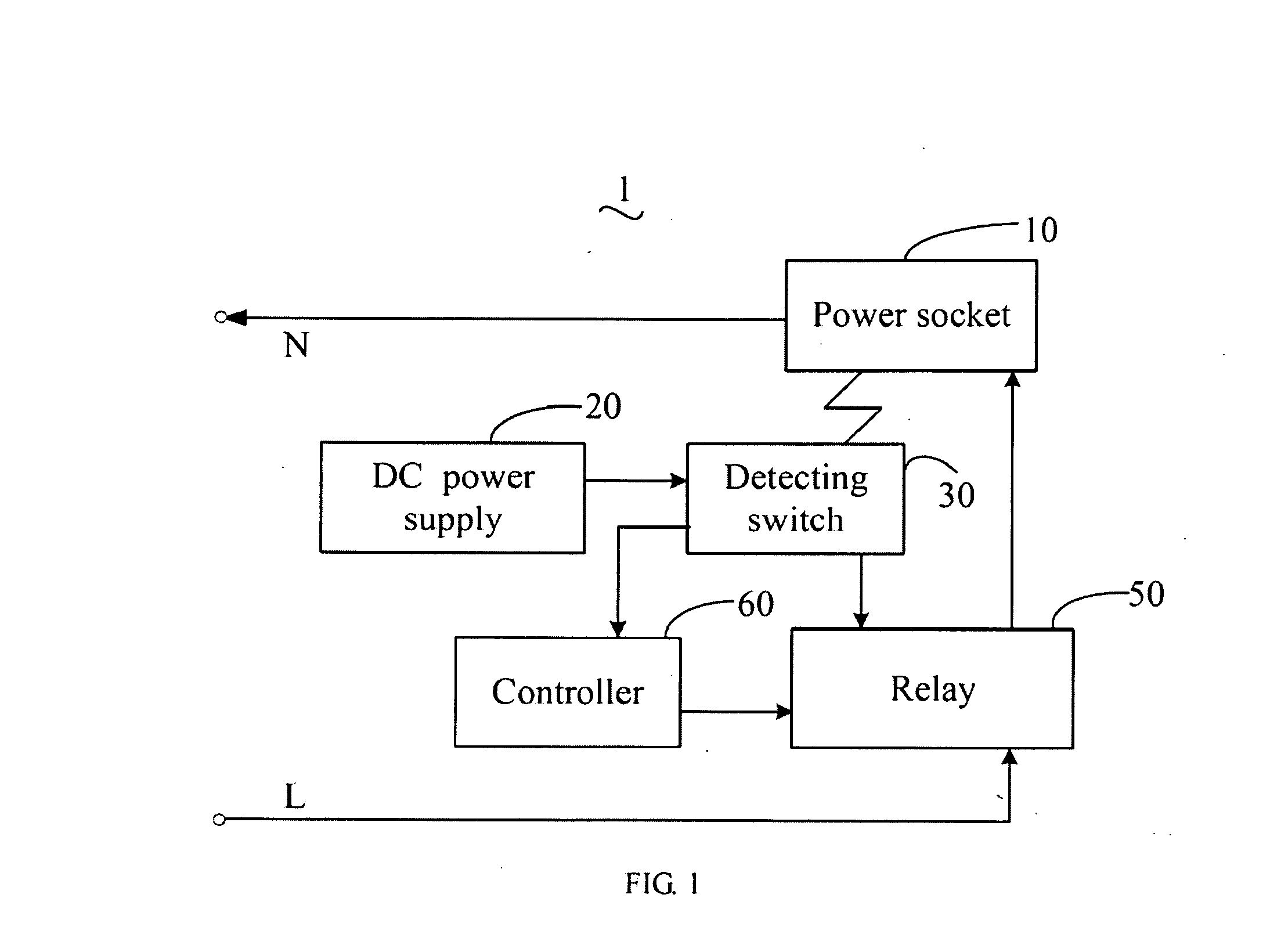
[0015]FIG. 1 is a block diagram of an electrical receptacle 1 in accordance with an exemplary embodiment of the present invention. The electrical receptacle 1 includes: a power socket 10, a direct current (DC) power supply 20, a detecting switch 30, a relay 50, and a controller 60. A live wire (labeled as L) is connected to the power socket 10 via the relay 50 and a neutral wire (labeled as N) is connected to the power socket 10 directly. The DC power supply 20, the detecting switch 30, the relay 50, and the controller 60 form a circuit loop for detecting whether a power plug 2 (shown in FIG. 2) is inserted into the power socket 10. The detecting switch 30 is placed under the power socket 10 without any electrical connection with the power socket 10. An input terminal of the detecting switch 30 is connected to the DC power supply 20 for obtaining a DC supply. An output terminal of the detecting switch 30 is connected to the relay 50 for providing a control signal to control the rela...
PUM
 Abstract
Description
Claims
Application Information
 - R&D
- Intellectual Property
- Life Sciences
- Materials
- Tech Scout
- Unparalleled Data Quality
- Higher Quality Content
- 60% Fewer Hallucinations
Browse by: Latest US Patents, China's latest patents, Technical Efficacy Thesaurus, Application Domain, Technology Topic, Popular Technical Reports.
© 2025 PatSnap. All rights reserved.Legal|Privacy policy|Modern Slavery Act Transparency Statement|Sitemap|About US| Contact US: help@patsnap.com