
Intelligent Power Unit, and Applications Thereof

a power unit and intelligent technology, applied in the field of intelligent power units, can solve the problems of increasing the number of desired power transactions that cannot be implemented, the power network to operate, and the inability to implement desired power transactions, so as to reduce the cost of peak load power and reduce the congestion of transmission facilities

Inactive Publication Date: 2009-04-09
GREENSMITH ENERGY MANAGEMENT SYST
View PDF22 Cites 132 Cited by
  • Summary
  • Abstract
  • Description
  • Claims
  • Application Information

AI Technical Summary

Benefits of technology

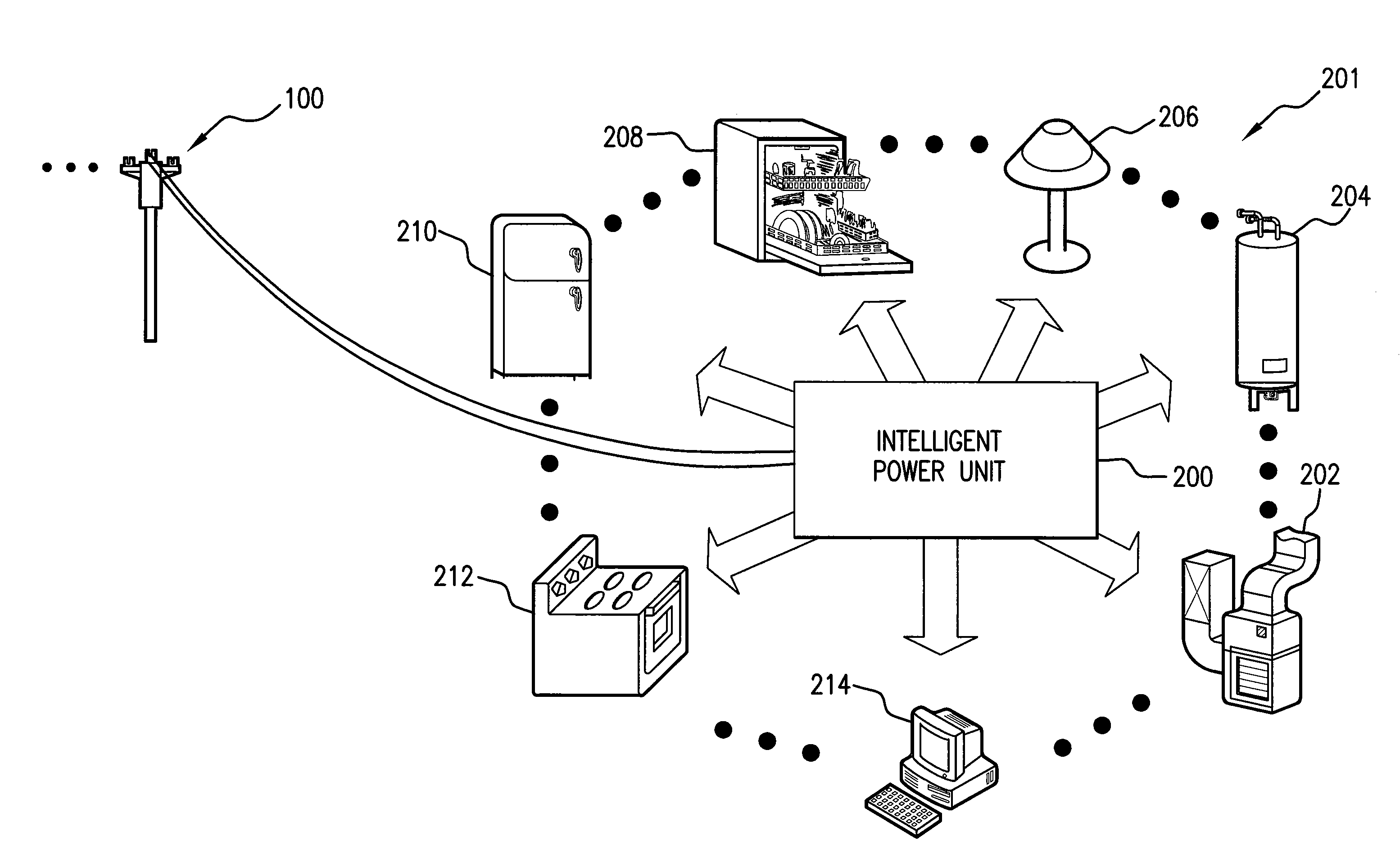
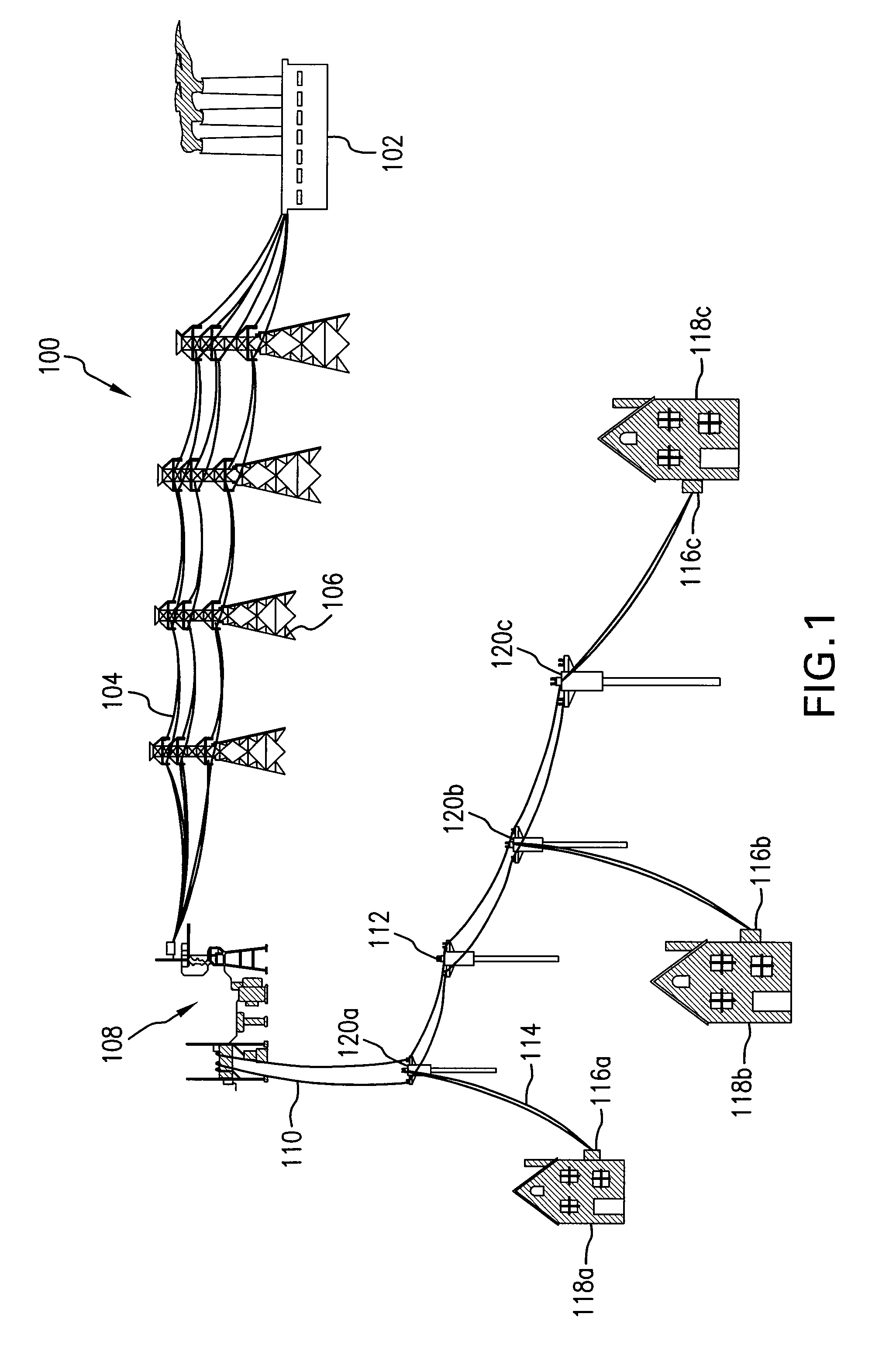
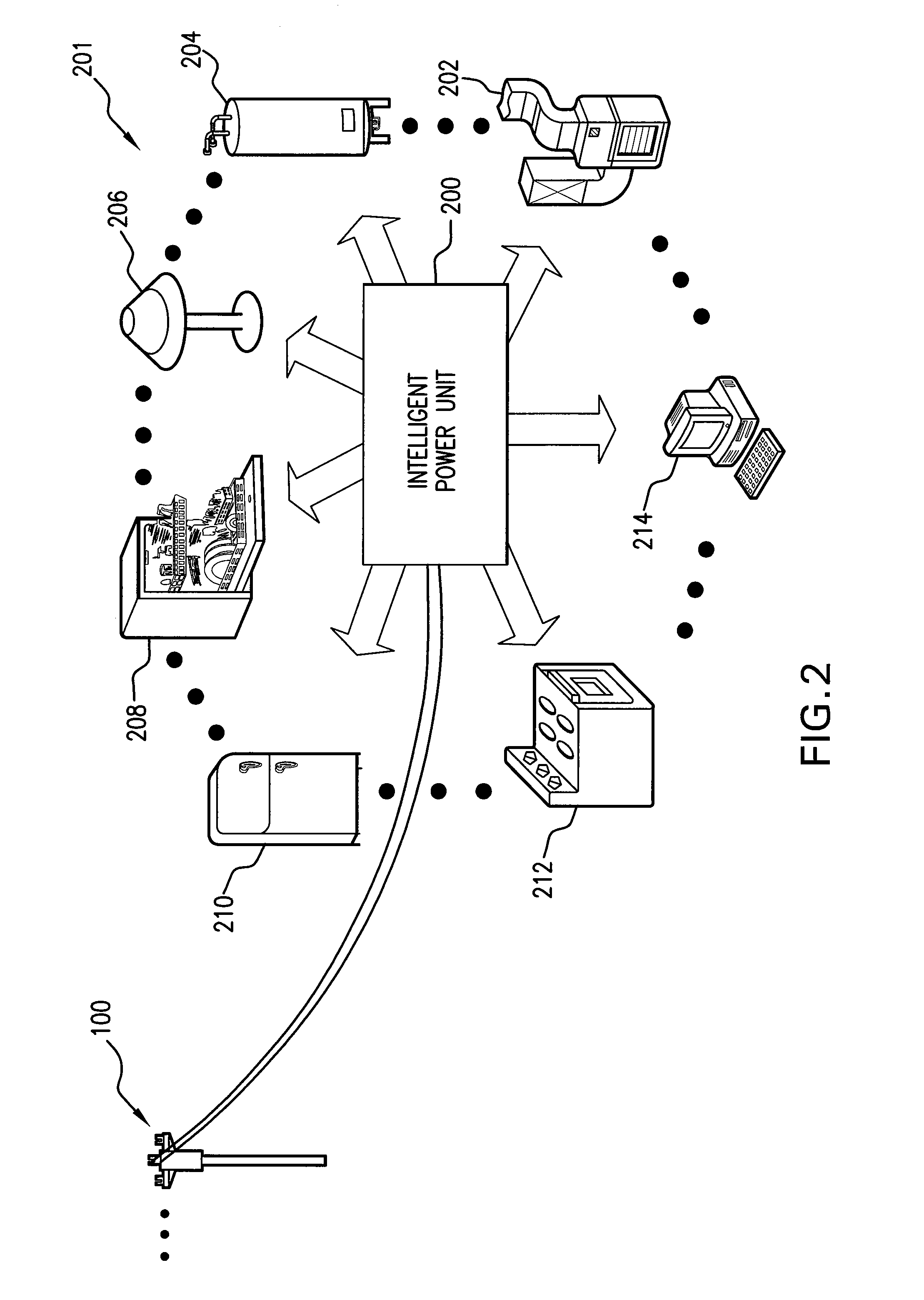
[0004]The present invention provides an intelligent power unit, and applications thereof. In an embodiment, the intelligent power unit includes a battery, a power switch, and a control unit. The control unit receives price information and operates the power switch based on the price information to charge the battery during periods of relatively low electrical energy prices. During periods of relatively high electrical energy prices, the control unit cause the energy stored in the battery to be used to power attached loads. The price information provided to the control unit can be actual price information regarding the cost to generate electrical power, estimated price information, or contract price information. It is a feature of the intelligent power unit of the present invention that it can be used to shift a utility's electrical power demand in time and thus present opportunities to substantially reduce the cost paid for peak load power as well as reduce congestion of transmission facilities.

Problems solved by technology

Deregulation and shifting power flows, however, are forcing the power network to operate in ways it was never intended.
In the United States, for example, the number of desired power transactions that cannot be implemented due to transmission bottlenecks continues to increase each year.
In some regions, the increase in electric power demand is such that periods of peak demand are dangerously close to exceeding the maximum supply levels that the electrical power industry can generate and transmit.

Method used


Image

  • Intelligent Power Unit, and Applications Thereof
  • Intelligent Power Unit, and Applications Thereof
  • Intelligent Power Unit, and Applications Thereof

Examples


Embodiment Construction

[0027]The present invention provides an intelligent power unit, and applications thereof. In the detailed description of the invention herein, references to “one embodiment”, “an embodiment”, “an example embodiment”, etc., indicate that the embodiment described may include a particular feature, structure, or characteristic, but every embodiment may not necessarily include the particular feature, structure, or characteristic. Moreover, such phrases are not necessarily referring to the same embodiment. Further, when a particular feature, structure, or characteristic is described in connection with an embodiment, it is submitted that it is within the knowledge of one skilled in the art to effect such feature, structure, or characteristic in connection with other embodiments whether or not explicitly described.

[0028]In an embodiment, an intelligent power unit according to the present invention includes a battery, a power switch, and a control unit. The control unit receives price inform...


PUM


Abstract

The present invention provides an intelligent power unit, and applications thereof. In an embodiment, the intelligent power unit includes a battery, a power switch, and a control unit. The control unit receives price information and operates the power switch based on the price information to charge the battery during periods of relatively low electrical energy prices. During periods of relatively high electrical energy prices, the control unit cause the energy stored in the battery to be used to power attached loads. The price information provided to the control unit can be actual price information regarding the cost to generate electrical power, estimated price information, or contract price information. It is a feature of the intelligent power unit of the present invention that it can be used to shift a utility's electrical power demand in time.

Description

FIELD OF THE INVENTION[0001]The present invention generally relates to energy management. More particularly, it relates to an intelligent power unit, and applications thereof.BACKGROUND OF THE INVENTION[0002]Electricity and the power network used to transmit and distribute it are vital. Deregulation and shifting power flows, however, are forcing the power network to operate in ways it was never intended. In the United States, for example, the number of desired power transactions that cannot be implemented due to transmission bottlenecks continues to increase each year. This trend, along with a trend of increased electric power demand, has pushed the capacity of many transmission lines to their design limits. In some regions, the increase in electric power demand is such that periods of peak demand are dangerously close to exceeding the maximum supply levels that the electrical power industry can generate and transmit.[0003]What are needed are new systems, methods, and apparatuses th...

Claims


Application Information

Patent Timeline
IPC IPC(8): G01R11/56
CPCG01R21/1335Y04S10/60G06Q50/06Y04S10/50
Inventor SMITH, RODNEY G.WERBOS, LUDMILLA D.WERBOS, PAUL J.
Owner GREENSMITH ENERGY MANAGEMENT SYST
Learn More