Sheet conveying device and image recording apparatus including the sheet conveying device

Active Publication Date: 2009-04-02
BROTHER KOGYO KK
View PDF5 Cites 20 Cited by
  • Summary
  • Abstract
  • Description
  • Claims
  • Application Information

AI Technical Summary

Benefits of technology

[0011]The stopper is provided such that the leading end of the sheet discharged onto the tray is brought into contact with the stopper. Thus, owing to the stopper, the sheet is prevented from dropping from the tray. There is a case in which a length of the discharged sheet (as measured in the discharging direction) is larger than a distance between the stopper and a proximal end of the tray (as measured in the discharging direction), namely, a case in which the leading end of the discharged sheet is brought into contact with the stopper before discharge of the sheet by the sheet discharger is completed. In such as case, while the leading end of the sheet is being in contact with the stopper, the sheet is forced to be moved further in the discharging direction. However, in the sheet conveying device in which the guide is located on the upstream side of the stopper, the sheet is warped when being moved along the guide of the tray, so as to have the downwardly convex shape in the cross section perpendicular to the discharging direction. Owing to the downwardly convex shape in which its widthwise intermediate portion is downwardly convex relative to its widthwise opposite ends, the thus warped sheet is given a high degree of rigidity and is accordingly made difficult to be bent in the discharging direction, so that the sheet can pass over the stopper without the sheet being bent in the discharging direction, although the leading end of the sheet is brought into contact with the stopper. Consequently, it is possible to prevent jamming of the sheet. It is noted that the present sheet conveying device may be either used to either convey a recording sheet as the sheet in an image recording apparatus or used as an automatic document feeder to convey a document as the sheet in an image reading apparatus such as a scanner apparatus.

Problems solved by technology

This state, which could be caused where the stopper 148 is movable in the discharging direction or the discharged recording sheet 137 has such a large length that its leading end reaches a downstream side of the stopper 148 in the discharging direction, could cause a risk of problematic jamming of the recording sheet 137.
Such a problem could occur not only where the sheet supplying cassette 149 is used for supplying a recording sheet in an image recording apparatus but also where it is used for supplying a document in a scanner apparatus.

Method used


Image

  • Sheet conveying device and image recording apparatus including the sheet conveying device
  • Sheet conveying device and image recording apparatus including the sheet conveying device
  • Sheet conveying device and image recording apparatus including the sheet conveying device

Examples


Embodiment Construction

[0029]There will be described an embodiment of the present invention, by reference to the accompanying drawings. It is noted that the embodiment will be described for illustrative purpose only and that the invention may be embodied with various changes, modifications and improvements, which may occur to those skilled in the art, without departing from the spirit of the invention defined in the appended claims.

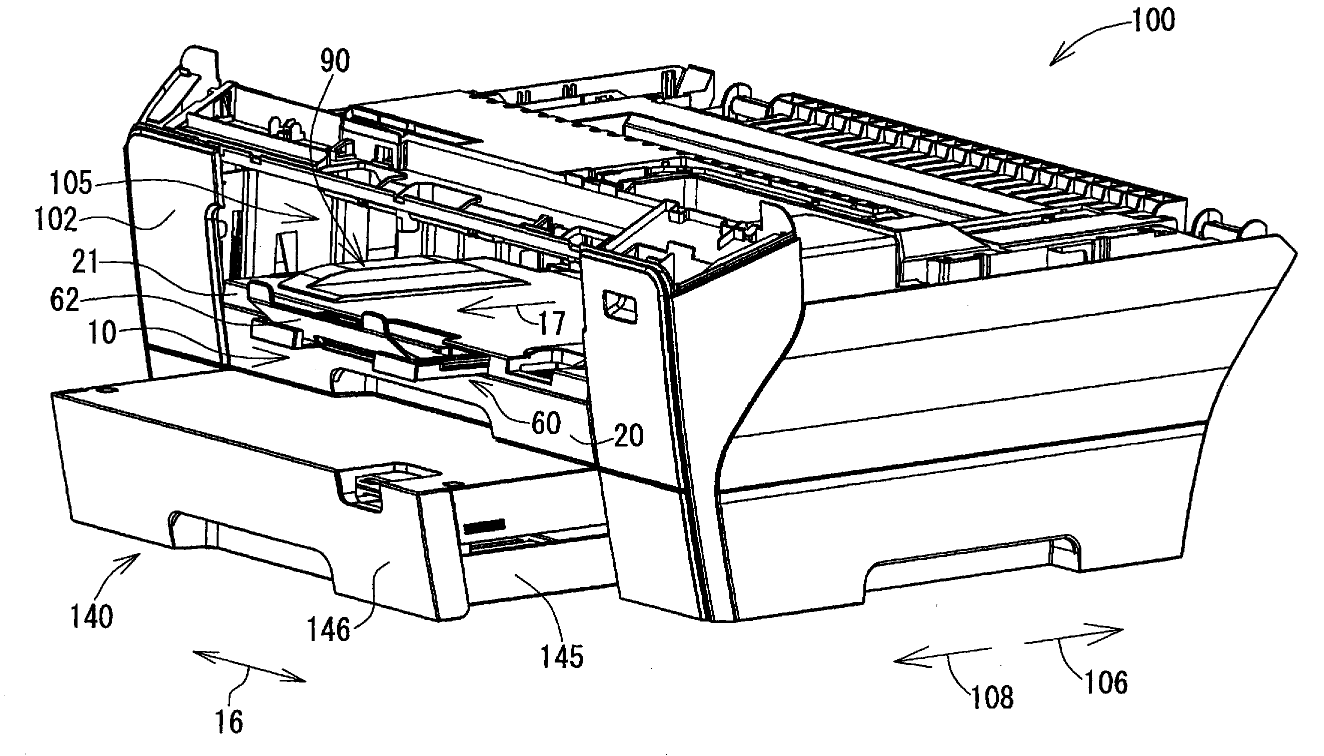
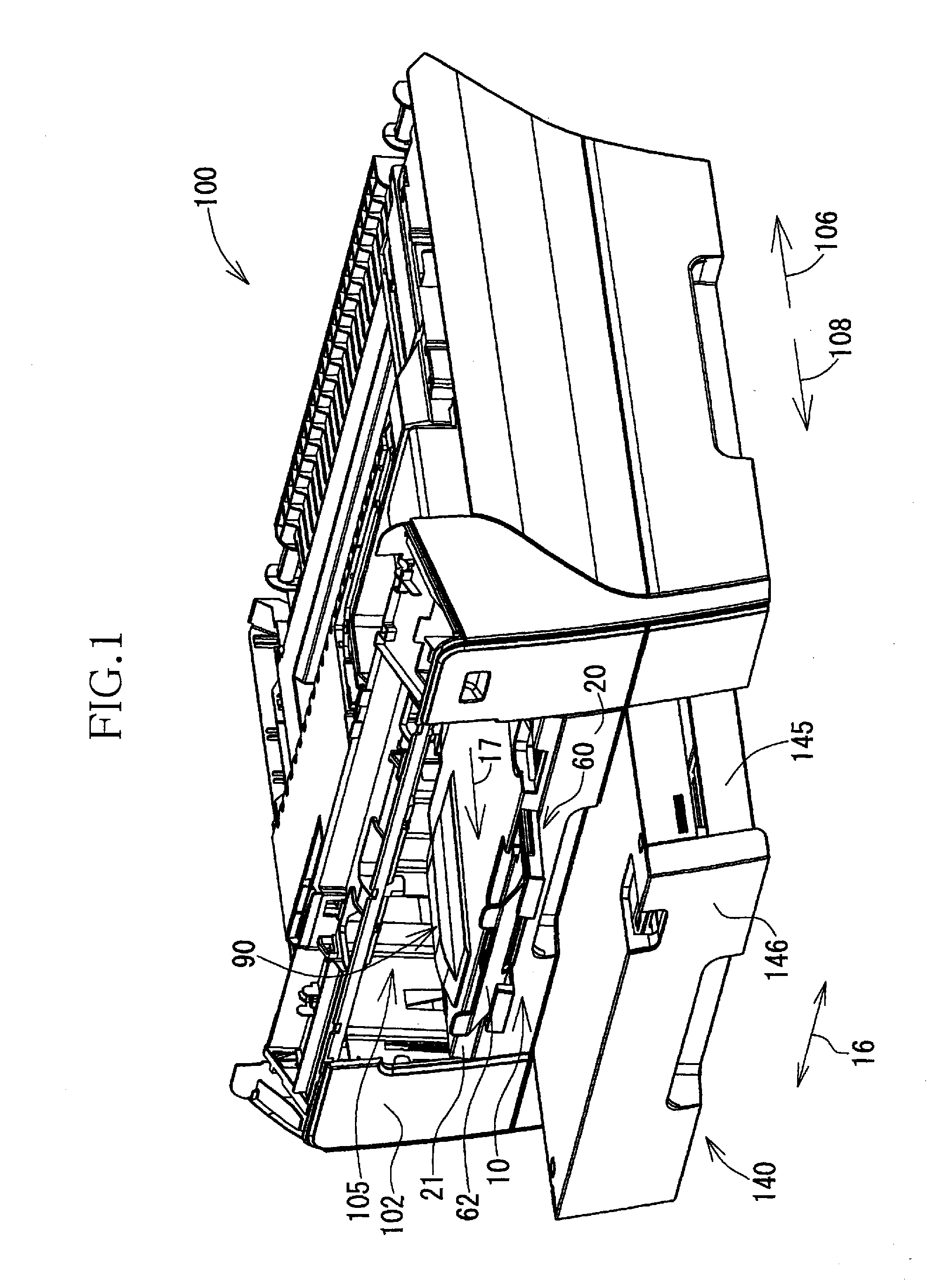
[0030]FIG. 1 shows an image recording apparatus in the form of an inkjet printer 100 that is constructed according to an embodiment of the invention. As shown in FIG. 1, the printer 100 has a generally rectangular parallelepiped shape, and its horizontal dimension (i.e., width and depth) is larger than its vertical dimension (i.e., height). The printer 100 has an opening 105 in its front side surface 102, thereby making it possible to introduce a sheet-supplying cassette 10 (see FIGS. 3 and 4) and a lower tray 140 (see FIG. 1) into a main body of the printer 100 via the opening...


PUM

PropertyMeasurementUnit
Sizeaaaaaaaaaa
Widthaaaaaaaaaa
Heightaaaaaaaaaa

Abstract

A sheet conveying device including: (a) a sheet discharger configured to discharge a sheet in a discharging direction; (b) a tray configured to receive the sheet discharged by the sheet discharger; (c) a stopper protruding upwardly from the tray; and (d) a guide provided by an upper surface of the tray and located on an upstream side of the stopper in the discharging direction, and configured to warp the discharged sheet such that the warped sheet has a downwardly convex shape in its cross section that is perpendicular to the discharging direction, for thereby allowing a leading end of the warped sheet to pass over the stopper and to be positioned on a downstream side of the stopper in the discharging direction.

Description

CROSS REFERENCE TO RELATED APPLICATION[0001]This application claims priority from Japanese Patent Application No. 2007-255668 filed on Sep. 28, 2007, the disclosure of which is herein incorporated by reference in its entirety.BACKGROUND OF THE INVENTION[0002]1. Field of the Invention[0003]The present invention relates to a sheet conveying device for conveying a sheet so as to discharge the sheet onto a tray, and also to an image recording apparatus including the sheet conveying device.[0004]2. Discussion of Related Art[0005]In an image reading apparatus equipped with an automatic document feeder (ADF), a document disposed on a document tray is conveyed along a path, an image carried on the document is read in the process of conveyance of the document. After the image has been read, the document is discharged onto an exit tray. As an example of such an image reading apparatus, JP-H06-247608A discloses an apparatus in which a haul member and ribs are provided on an upper surface of an...

Claims


Application Information

Patent Timeline
IPC IPC(8): B65H1/00
CPCB65H31/20B65H2301/51214B65H2301/5122B65H2801/06B65H2405/1124B65H2405/31B65H2405/3322B65H2405/11164
Inventor WAKAKUSA, KEISUKEIZUCHI, MASATOSHI
Owner BROTHER KOGYO KK
Why Eureka
Try Eureka