
Jewelry ring and method for the production thereof

Inactive Publication Date: 2009-04-02
MONTBLANC SIMPLO
View PDF4 Cites 0 Cited by
  • Summary
  • Abstract
  • Description
  • Claims
  • Application Information

AI Technical Summary

Benefits of technology

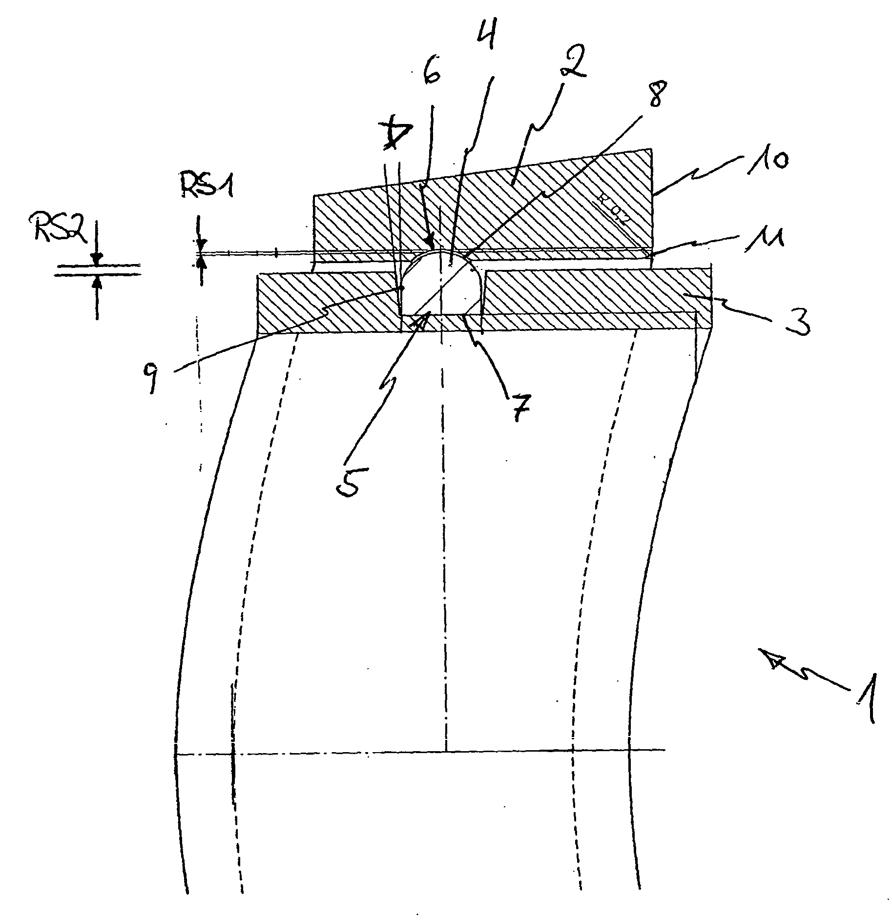
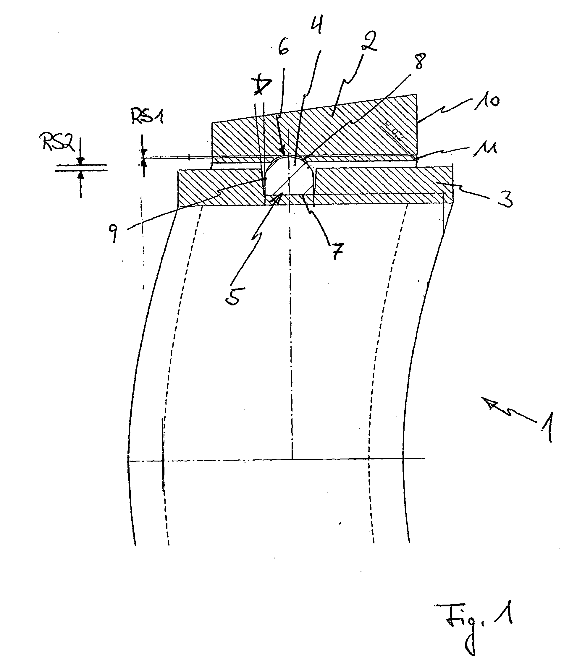
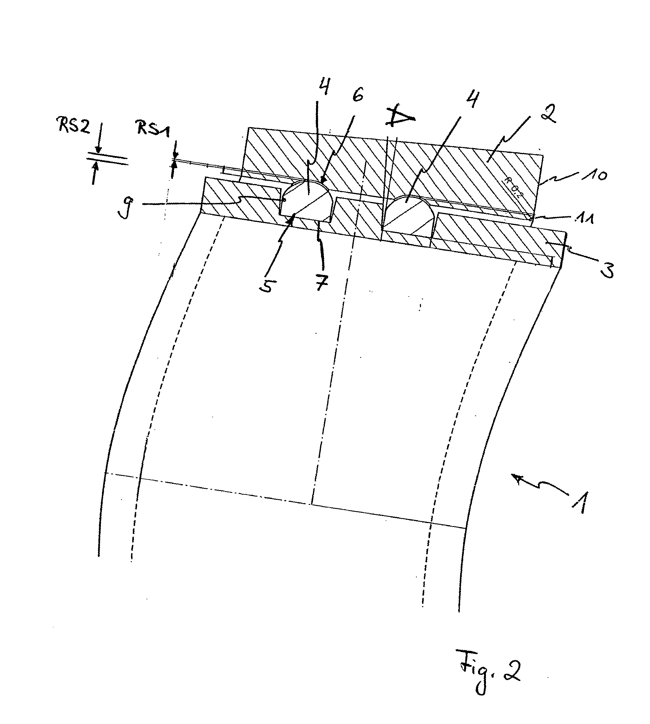
[0005]Therefore, the present invention is based on the idea to provide a ring comprising two separate individual rings that are fitted into one another in such a way that one ring is positioned concentrically with respect to the other ring, so that both rings can be rotated relative to each other. To prevent the occurrence of undesirable friction between the two rings during such a rotation, there is at least one sliding ring inserted between the two rings, which serves as bearing surface for at least one of the two rings, so it can be rotated, with respect to the respective other ring, around it without the occurrence of signs of wear and tear.
[0018]In order to guarantee a securing of the position between the first and second rings, prior to mounting of the at least one sliding ring, both in the inner surface area of the first ring and in the outer surface area of the second ring at least one circular recess each is formed, into each of which the at least one sliding ring partially engages. These recesses are therefore designed in such a way that the at least one sliding ring is essentially entirely circumferentially accommodated, so that axial movements of the two rings with respect to one another are essentially eliminated.

Problems solved by technology

However, this need to play or need for distraction, which often arises out of boredom or nervousness, often, and preferably with rings of inferior material quality, results in both inner and outer circumference of the ring being subject to wear and possible coatings being removed.
These rings, which were brought on the market for the first time by the Cartier company under the name Cartier ring, also often invite the ring wearer to play since such a ring is easily moved back and forth in lengthwise direction of the finger due to its mechanical kinematic properties, which, in turn, however results in heavy signs of wear on the individual rings.

Method used


Image

  • Jewelry ring and method for the production thereof
  • Jewelry ring and method for the production thereof
  • Jewelry ring and method for the production thereof

Examples


Embodiment Construction

[0004]Due to the need to play or need for distraction of many ring wearers, and due to the wear and tear that is associated with it, there is a need for a ring which downright invites to play, however, without being subject to undesirable signs of wear in the process.

[0005]Therefore, the present invention is based on the idea to provide a ring comprising two separate individual rings that are fitted into one another in such a way that one ring is positioned concentrically with respect to the other ring, so that both rings can be rotated relative to each other. To prevent the occurrence of undesirable friction between the two rings during such a rotation, there is at least one sliding ring inserted between the two rings, which serves as bearing surface for at least one of the two rings, so it can be rotated, with respect to the respective other ring, around it without the occurrence of signs of wear and tear.

[0006]In particular, the ring according to the invention is a jewelry ring w...


PUM

PropertyMeasurementUnit
Shapeaaaaaaaaaa
Areaaaaaaaaaaa
Surface areaaaaaaaaaaa

Abstract

The present invention generally relates to a jewelry ring (1) and a method for the production of such a jewelry ring (1). The jewelry ring consists of a first ring (2) having an inner surface area, a second ring (3) and a sliding ring (4), the latter is located between the first ring (2) and the second ring (3) to ease a preferably frictionless twistability of the two rings to each other.

Description

TECHNICAL FIELD[0001]The present invention generally relates to the technical field of jewelry production. In particular, the invention relates to a jewelry ring with a novel design and a method for the production of such a novel jewelry ring.BACKGROUND OF THE INVENTION[0002]Many ring wearers know the need or at least the habit to play with a ring they are wearing on one of their fingers, the ring being rotated about the finger or moved back and forth on the finger by the wearer. However, this need to play or need for distraction, which often arises out of boredom or nervousness, often, and preferably with rings of inferior material quality, results in both inner and outer circumference of the ring being subject to wear and possible coatings being removed.[0003]Furthermore, for example rings are known which consist of several individual rings, each of which is intertwined, so that they can be pushed together onto a finger. These rings, which were brought on the market for the first ...

Claims


Application Information

Patent Timeline
IPC IPC(8): A44C9/00A44C27/00
CPCY10T29/49593A44C9/003
Inventor HERING, THORSTEN
Owner MONTBLANC SIMPLO
Learn More