Sweeping broom apparatus having a surface tracking air blast nozzle

a technology of air blast nozzle and sweeping broom, which is applied in the direction of cleaning equipment, suction cleaners, road cleaning, etc., can solve the problems of affecting the effect of having the air blast nozzle too close to the surface and being highly undesirabl

Inactive Publication Date: 2009-04-02
VANDERLINDEN ROGER P
View PDF7 Cites 6 Cited by
  • Summary
  • Abstract
  • Description
  • Claims
  • Application Information

AI Technical Summary

Benefits of technology

[0007]In accordance with one aspect of the present invention there is disclosed a novel sweeping broom apparatus for use with a vehicle. The sweeping broom apparatus comprises a main body having a debris receiving inlet and a connecting means for operatively connecting the main body to a vehicle. A broom shroud has an open bottom defined by a bottom edge, and has a front end and a back end, and defining a longitudinal horizontal axis extending between the front end and the back end. An airflow obstructing means is disposed around the bottom edge of the broom shroud for substantially obstructing the egress of air from between the bottom edge of the broom shroud and the surface being cleaned. There is a forwardly facing debris outlet in the broom shroud for permitting the directed egress of debris therefrom as a forwardly propelled stream of debris. A main sweeping broom is mounted within the broom shroud for propelling debris forwardly from the surface being cleaned generally along the longitudinal horizontal axis, thereby creating a stream of debris propelled forwardly through the forwardly facing debris outlet. An air blast nozzle is connected in fluid communication to a source of compressed air for receiving compressed air therefrom. There is a nozzle mounting means for mounting the air blast nozzle for movement between a lower position whereat the air blast nozzle is disposed adjacent the surface being cleaned and to emit air in a forward and downward direction to impact on the surface being cleaned, and a raised impact-absorbing position. There is also a biasing means for biasing the air blast nozzle to the lower position.
[0008]Other advantages, features and characteristics of the present invention, as well as methods of operation and functions of the related elements of the structure, and the combination of parts and economies of manufacture, will become more apparent upon consideration of the following detailed description and the appended claims with reference to the accompanying drawings, the latter of which is briefly described herein below.

Problems solved by technology

Preferably, the air blast nozzle is disposed in close relation to the surface being cleaned in order to be as effective as possible; however, it is detrimental to have the air blast nozzle too close to the surface being cleaned since the air blast nozzle may readuly become damaged.
As the street sweeper travels over a surface being cleaned, such as a road or the like, the air blast nozzle is subjected to the undulations in the road, and also can impact on rocks or other objects on the surface being cleaned, thus potentially causing damage, which is highly undesirable.

Method used


Image

  • Sweeping broom apparatus having a surface tracking air blast nozzle
  • Sweeping broom apparatus having a surface tracking air blast nozzle
  • Sweeping broom apparatus having a surface tracking air blast nozzle

Examples


Embodiment Construction

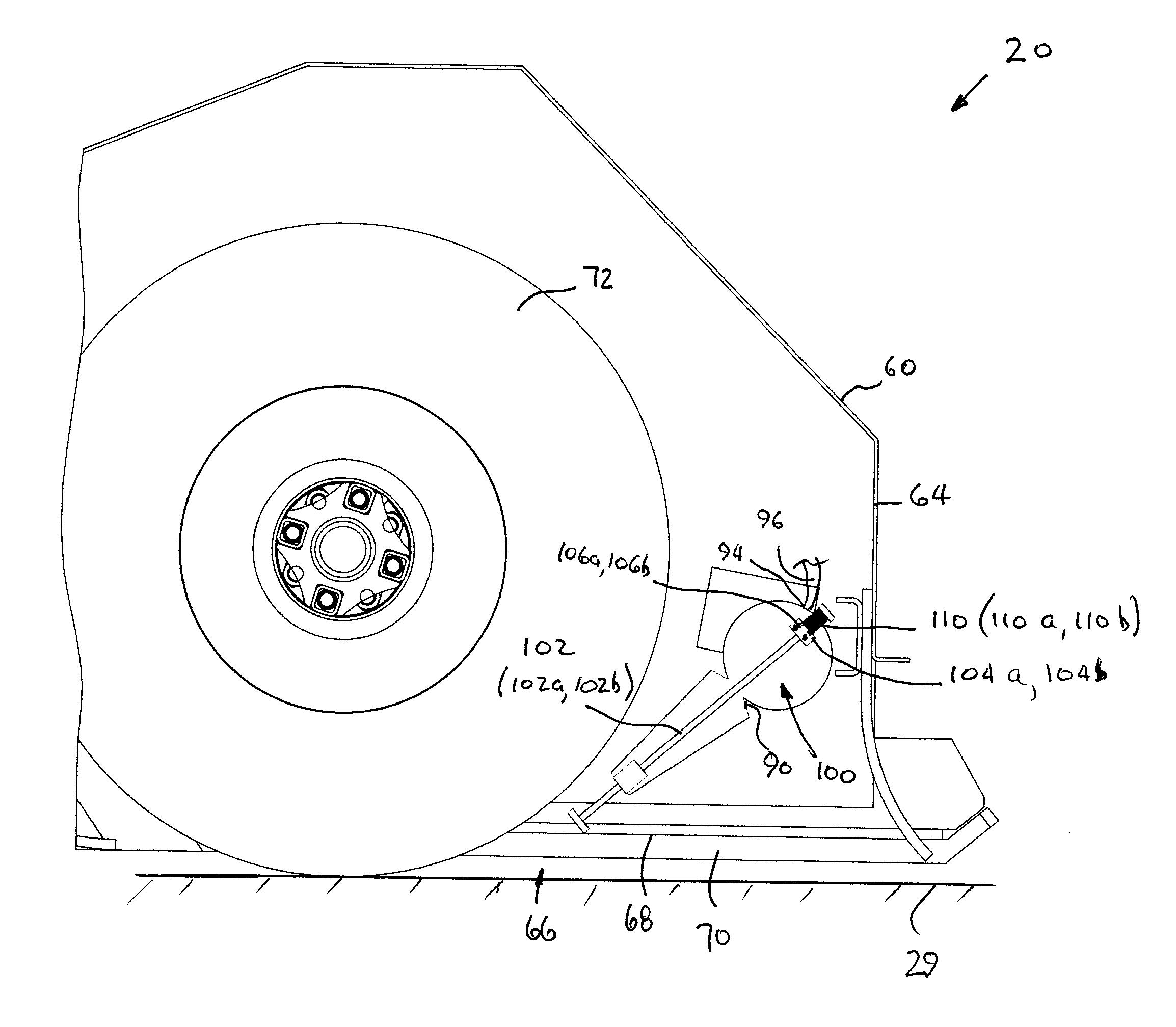
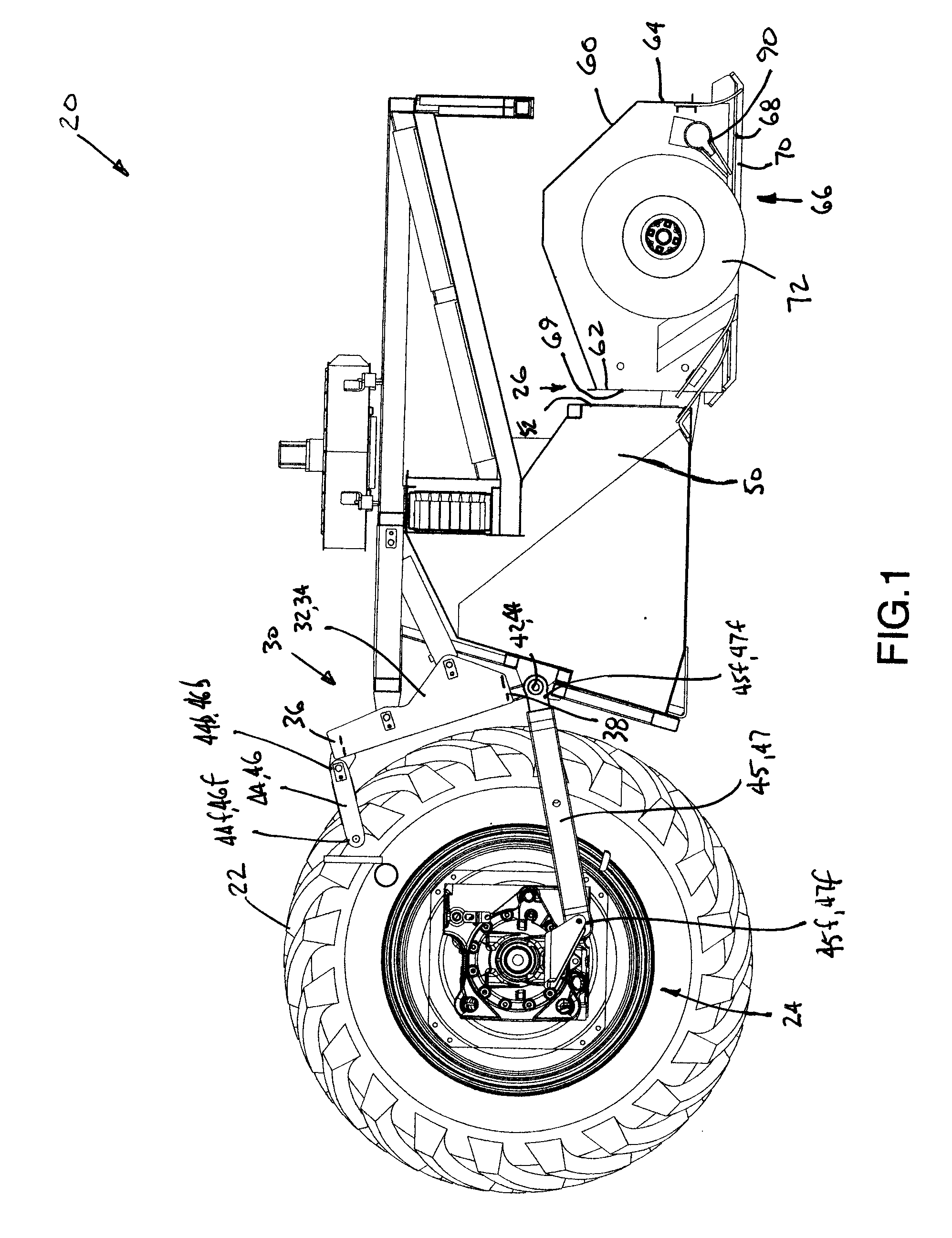
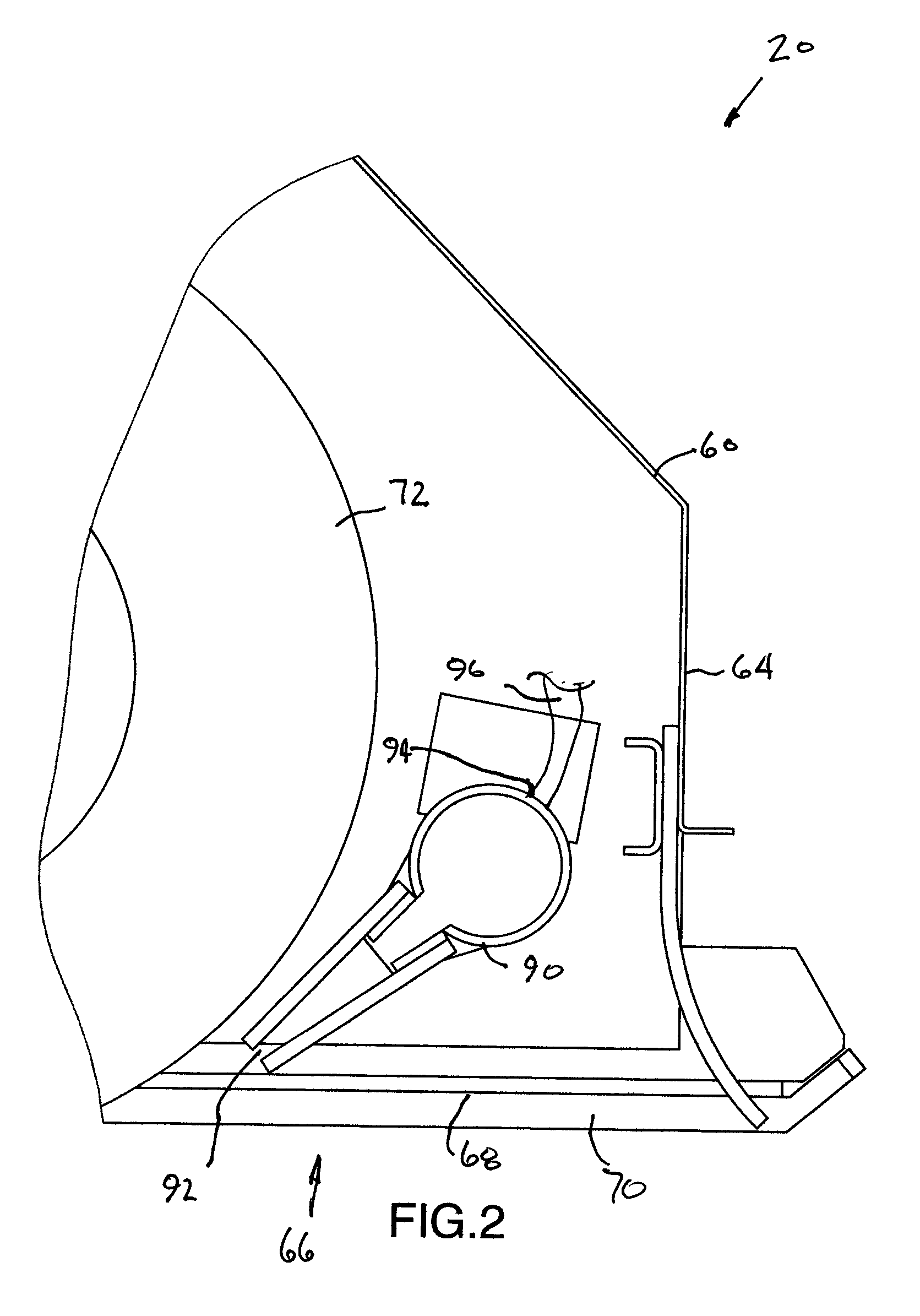
[0014]Reference will now be made to FIGS. 1 through 4, which show a preferred embodiment of the sweeping broom apparatus of the present invention, as indicated by general reference numeral 20. The sweeping broom apparatus 20 is for use with a vehicle, such as a tractor 22, which is only partially shown. The tractor has a three point hitch 24 for receiving the sweeping broom apparatus 20 in supported relation thereon.

[0015]The sweeping broom apparatus 20 comprises a main body 21 having a debris receiving inlet 52 for receiving debris thereinto. There is also connecting means, as indicated by general reference numeral 30, for operatively connecting the sweeping broom apparatus 20 in trailing relation to the vehicle, such that the sweeping broom apparatus 20 is received in supported relation on the pair of rearwardly extending mounting arms 23 of the three point hitch 24. The connecting means 30 comprises a generally vertically oriented base member 30 having left and right generally ve...


PUM


Abstract

A sweeping broom apparatus for use with a vehicle comprises a main body with a debris receiving inlet, and a broom shroud with an open bottom. Airflow obstructing flaps are disposed around the bottom edge of the broom shroud. A forwardly facing debris outlet in the broom shroud permits the directed egress of debris therefrom as a forwardly propelled stream of debris. A main sweeping broom is mounted within the broom shroud for propelling debris forwardly, thereby creating a stream of debris propelled forwardly through the forwardly facing debris outlet. An air blast nozzle is connected in fluid communication to a source of compressed air for receiving compressed air therefrom. There is a nozzle mount for mounting the air blast nozzle for movement between a lower position whereat the air blast nozzle is disposed adjacent the surface being cleaned and to emit air in a forward and downward direction to impact on the surface being cleaned, and a raised impact-absorbing position. There is also a biasing spring for biasing the air blast nozzle to the lower position.

Description

[0001]This application is a non-provisional application claiming priority from U.S. Provisional Patent Application Ser. No. 60 / 975,041 filed on Sep. 25, 2007, which is herein incorporated by reference.FIELD OF THE INVENTION[0002]The present invention relates to street sweeping vehicles, and more particularly to dustless street sweeping vehicles.BACKGROUND OF THE INVENTION[0003]Conventional street sweepers have a main vehicle body and a hopper supported by the main vehicle body. In mechanical type street sweepers, there is a debris elevator at the back end of the vehicle. A large cylindrically shaped rotating sweeping broom is disposed immediately behind the elevator. The large cylindrically shaped sweeping broom contacts the surface being cleaned so as to propel debris forwardly to the elevator. The debris elevator receives debris from a main sweeping broom and deposits the debris into the hopper.[0004]Similarly, for re-circulating types street sweepers and vacuum type street sweepe...

Claims


Application Information

Patent Timeline
Patent Type & Authority Applications(United States)
IPC IPC(8): E01H1/05
CPCE01H1/0818
Inventor VANDERLINDEN, ROGER P.
Owner VANDERLINDEN ROGER P
Why Eureka
Try Eureka