
Method and apparatus for improved flow limitation detection of obstructive sleep apnea

a technology for obstructive sleep apnea and detection methods, applied in the field of improved methods and apparatus for the diagnosis and treatment of respiratory conditions, can solve the problems of not being able to detect flow limitation in certain types of flow patterns, affecting the function of the valve, so as to remove any expiratory pause

Active Publication Date: 2009-03-26
RESMED LTD
View PDF11 Cites 9 Cited by
  • Summary
  • Abstract
  • Description
  • Claims
  • Application Information

AI Technical Summary

Benefits of technology

[0021]Hence it is an aspect of the invention to estimate the extent of flow limitation in patient breath by the extent to which the position of peak flow deviates from the center of the inspiration flow curve.
[0022]It is a further aspect of the invention to estimate the flow limitation by the extent to which the relative mean amplitude of different parts of the breath deviate from the pattern exhibited by normal breaths.
[0015]The present invention involves an improved method and apparatus for detecting some forms of respiration obstruction based upon the flattening of the inspiratory airflow.

Problems solved by technology

Obstructive Sleep Apnea (OSA), a syndrome that includes apnea, hypopnea and heavy snoring, causes sleep disruption that brings about serious health problems possibly including types of heart disease.
One problem that arises is that the appropriate pressure varies during the night as the person goes through different stages of sleep.
All these disclosed techniques fail to detect flow limitation in certain types of flow patterns, particularly the M-wave pattern.
More generally, flow limitation in the inspiratory patterns that present with leading or lagging overshoot, is not appropriately detected.
The flow limitation detection / estimation technique described by the prior art is also expensive in terms of digital processing power, and the accuracy of flow detection required.
Therefore its utility in low cost electronic / software platforms is limited.

Method used


Image

  • Method and apparatus for improved flow limitation detection of obstructive sleep apnea
  • Method and apparatus for improved flow limitation detection of obstructive sleep apnea
  • Method and apparatus for improved flow limitation detection of obstructive sleep apnea

Examples


second embodiment

[0076]In a second embodiment the method comprises 1) estimating peak flow in the middle portion (e.g. a third) of the wave 2) any point outside that portion (e.g. in the first and / or last third of the said wave) that exceeds the peak flow is reset to the average of the sample before and after. 3) The process continues until no sample in the outside portions is greater than the peak flow. This method again reduces the impact of the overshoot—while also maintaining the shape of the waveform.

[0077]In a third (preferred) embodiment the method consists of 1) Dividing the wave into n parts and calculate mean amplitudes for each part. 2) Apply logic to determine what sort of wave the pattern indicates. 3) If overshoot is indicated, mark flattening as low.

fourth embodiment

[0078]In a fourth embodiment the method consists of 1) Calculating estimate of flattening for every n samples in the middle half of the wave (e.g. calculate flattening for sample 16 . . . 24, 17 . . . 25, and so on). 2) Marking the flattening index as the value that corresponds to the lowest value obtained for all sample permutations.

Alternative Statistical Calculation for M-Shape Detection

[0079]An alternative embodiment of the invention uses a different measure to determine whether an inspiratory wave pattern has an M shape. The technique is to decompose the inspiratory wave into a vector of features (floating point numbers) and a matrix pair of basis vectors that are orthogonal. Normalizing the time interval so that inspiration begins at zero and ends at B radians, the basis vectors may be chosen to be sin (Bt) and sin (3Bt). The inspiratory waveform is thus fit to the curve a sin (Bt)+b sin (3Bt), where a and b are determined by fitting the basis vectors to the inspiratory wavefo...


PUM


Abstract

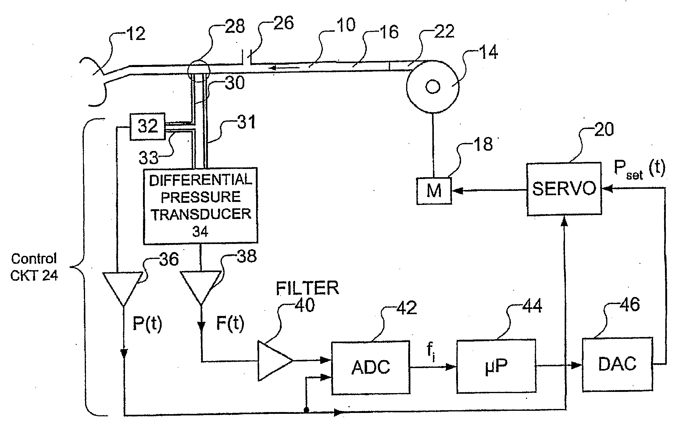
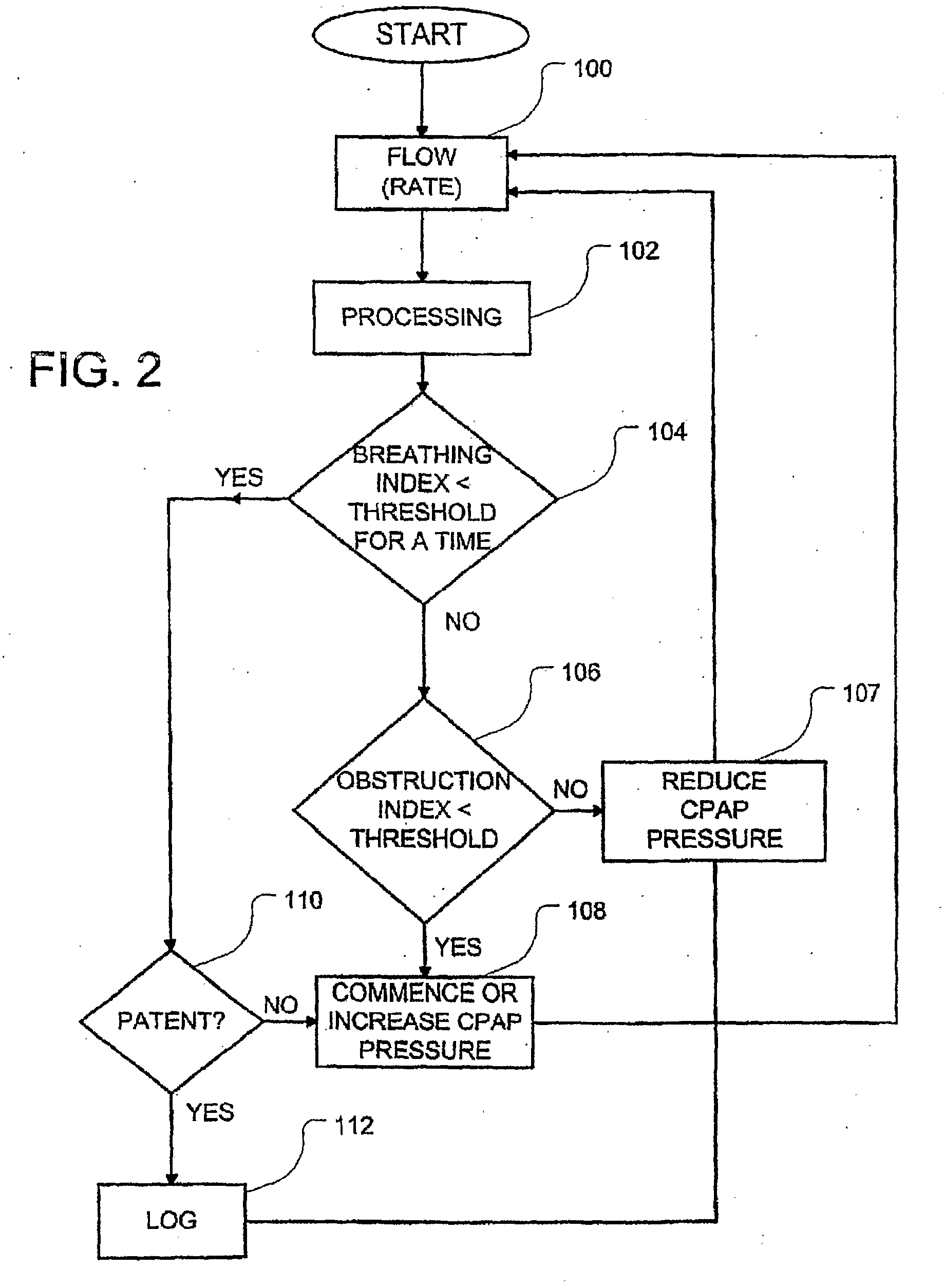
In a respiratory apparatus for treatment of sleep apnea and other disorders associated with an obstruction of a patient's airway and which uses an airflow signal, an obstruction index is generated which detects the flattening of the inspiratory portion of the airflow. The flattening index serves as an obstruction index used to differentiate normal and obstructed breathing. The obstruction index is based upon comparison of values of airflow in different sectors of the inspiratory peak of the wave function and is particularly suitable for distinguishing M shaped or square shaped respiratory patters indicative of partially obstructed airways.

Description

FIELD OF THE INVENTION[0001]This invention relates to an improved method and apparatus for the diagnosis and treatment of respiratory conditions including sleep apnea or hypopnea. In particular it relates to detecting either partial or complete obstruction of the airway of a patient, based upon an analysis of the time development of an inspiratory portion of a respiratory airflow curve. It also relates to apparatus that adjust treatment pressure to be applied by a CPAP ventilator.BACKGROUND OF THE INVENTION[0002]Obstructive Sleep Apnea (OSA), a syndrome that includes apnea, hypopnea and heavy snoring, causes sleep disruption that brings about serious health problems possibly including types of heart disease. OSA is-caused by the collapse of portions of a person's airway passage. The treatment of choice for OSA is the administration of Continuous Positive Airway Pressure (CPAP) to keep the patient's airway open. The air, usually in the pressure range 4-20 cm H2O, is supplied by a mot...

Claims


Application Information

Patent Timeline
IPC IPC(8): A61M16/00A61B5/374
CPCA61B5/087A61B5/4818A61M16/0051A61M16/06A61M2016/0021A61M2016/0027A61M16/0069A61B5/7225A61B5/4836A61M16/0066A61B5/7289A61B5/725A61M16/0875A61M2016/0036A61M16/026A61M16/022A61M16/024A61M16/021A61M2016/003A61M2016/0033A61M2016/0015A61M2016/0018A61M2205/3327A61M2205/3334A61M2205/3331A61M2205/3344A61M2205/33A61M2206/10A61M2230/005A61M2230/40
Inventor ARMITSTEAD, JEFFREY PETERSOMAIYA, CHINMAYEE
Owner RESMED LTD
Learn More