
Enhanced control for compression and decompression of sampled signals

a sample signal and compression technology, applied in the field of compression and decompression of sampled signals, can solve the problems of lossy compression, insufficient bit rate reduction, and distortion of the characteristics of the reconstructed signal

Inactive Publication Date: 2009-03-19
ALTERA CORP
View PDF9 Cites 61 Cited by
  • Summary
  • Abstract
  • Description
  • Claims
  • Application Information

AI Technical Summary

Benefits of technology

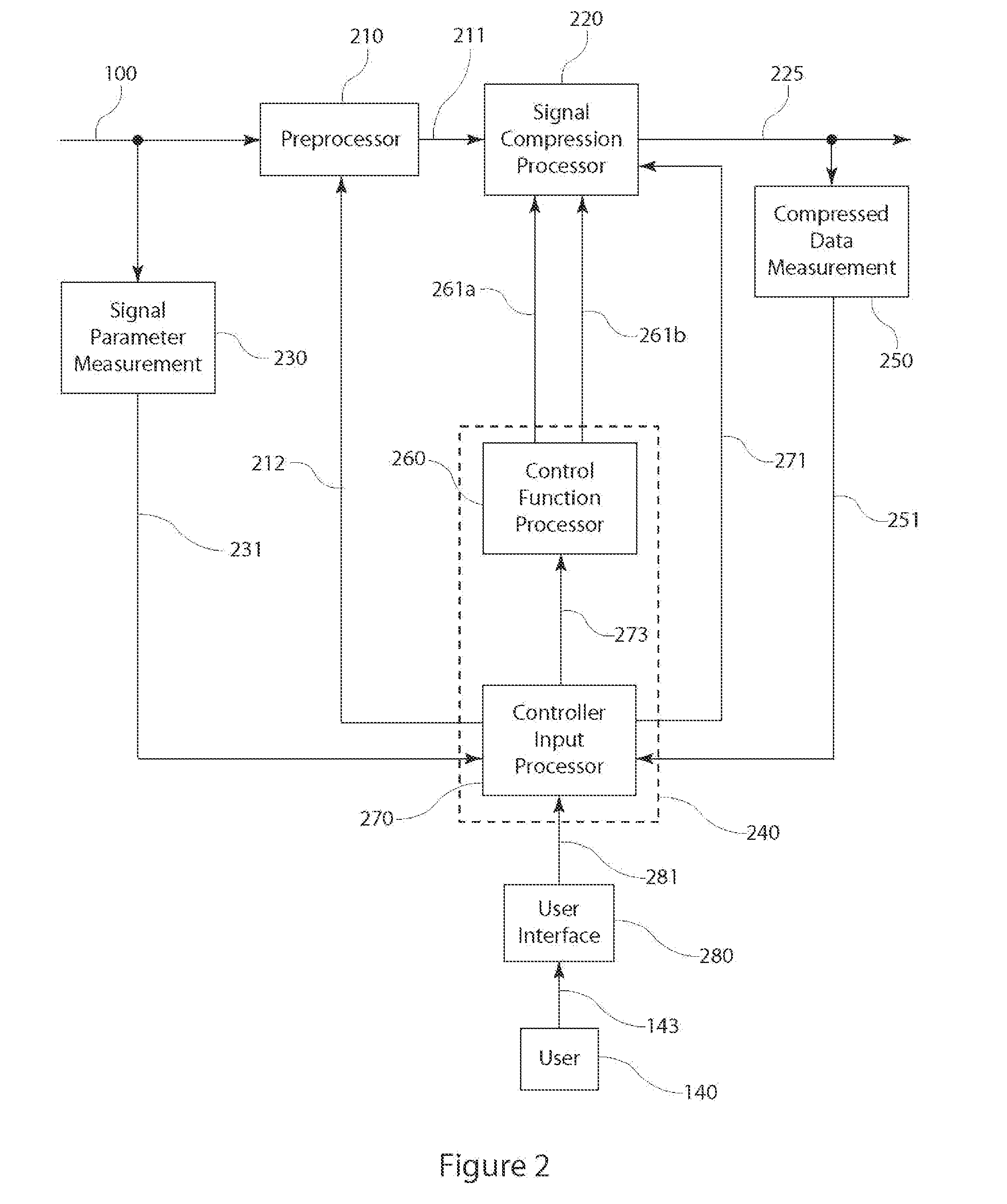
[0013]A graphical user interface (GUI) for the selection of control function characteristics includes a scale with a pointer. One end of the scale represents a minimum change to a particular control parameter and the other end represents a minimum change to a different control parameter. The location of the pointer on the scale indicates a value for a control function characteristic or a ratio parameter. When the scale represents the sample rate control parameter and the dynamic range control parameter, the pointer location indicates a value for the ratio parameter or other control function characteristic that indicates the relative changes in these two control parameters. The scale allows the user to select and coordinate the relative amounts of change to be applied to the selected control parameters.

Problems solved by technology

If lossless compression does not give adequate reductions in the bit rate of the compressed signal, then lossy compression may be necessary to provide sufficient reduction of the bit rate.
In lossy compression, the decompressed, or reconstructed, signal samples are similar, but not identical to, the original signal samples, creating distortion in the characteristics of the reconstructed signal.
Lossy compression creates a tradeoff between the bit rate of the compressed signal samples and the distortion in the reconstructed signal samples.
If there was a truncation in the frequency domain, Gibbs' phenomenon (ripple) can cause unwanted oscillations in the time domain reconstructed signal samples.
Amplitude distortion may also result from quantization of the transform coefficients.
Quantization of time domain samples or frequency domain transform coefficients both cause distortion in the amplitude of the reconstructed signal samples compared with the original signal samples.
In addition, applying coarser quantization will also increase quantization noise.
When the differences are added back in during decompression, the resulting reconstructed signal samples will have amplitude distortion and increased quantization noise resulting in a lower SNR.
Those skilled in the art recognize that distortion is a result of lossy compression.
The previous methods do not provide coordinated control over the relative distortions in signal characteristics.

Method used


Image

  • Enhanced control for compression and decompression of sampled signals
  • Enhanced control for compression and decompression of sampled signals
  • Enhanced control for compression and decompression of sampled signals

Examples


Embodiment Construction

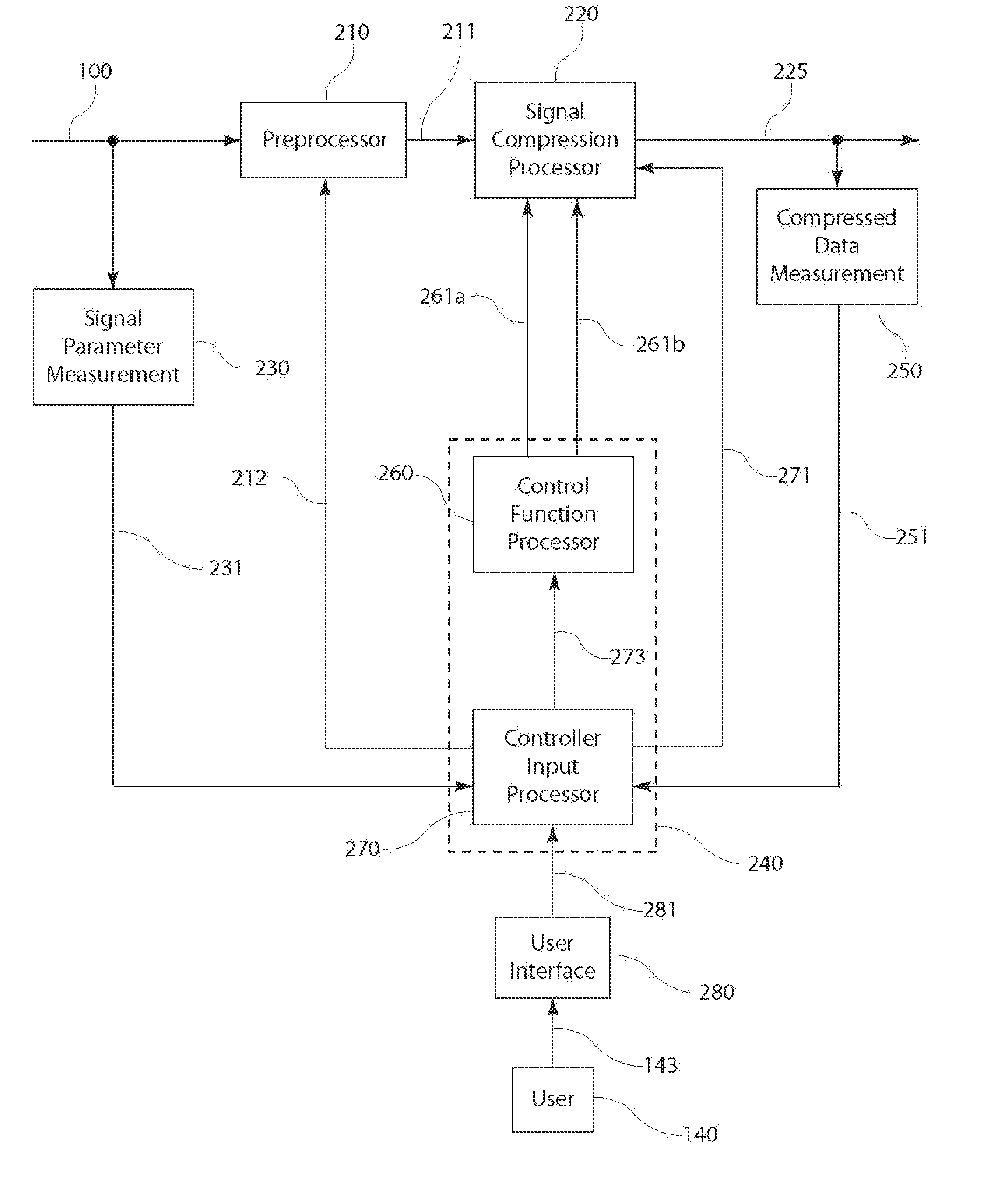
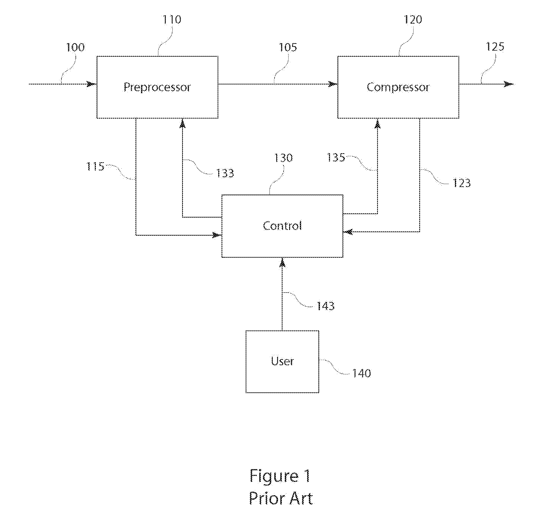
[0032]FIG. 1 is a block diagram of a signal compressor previously described in the '533 patent. The preprocessor 110 performs various selectable operations on the input signal samples 100 to produce signal samples 105 with lowpass or other desired characteristics for the compression operations of the compressor 120. Some of the preprocessor operations will be described below with respect to FIG. 9. The preprocessor 110 can also measure various characteristics of the signal samples, such as center frequency, noise floor and bandwidth. The compressor 120 applies selected operations that compress the preprocessed signal samples 105 including computing first or higher order differences, or derivatives, of the preprocessed signal samples, approximating certain signal samples through mathematical operations on other signal samples, encoding (such as Huffman encoding) and bit-packing. The control module 130 produces control parameters for operations of the preprocessor 110 and the compress...


PUM


Abstract

Control of signal compression is coordinated by selectively modifying control parameters affecting the bit rate, sample rate, dynamic range and compression operations. Selected control parameters are modified according to a control function. The control function can include a ratio parameter that indicates the relative or proportional amounts of change to the control parameters. Alternatively, the control function can be represented in a lookup table with values for the selected control parameters related by the control function. The input signal samples can be resampled according to a sample rate control parameter. The dynamic range of signal samples can be selectively adjusted according to a dynamic range control parameter to form modified signal samples. The resampling and dynamic range adjustment can be applied in any order. The modified signal samples are encoded according to a compression control parameter to form compressed samples. The encoder can apply lossless or lossy encoding.

Description

BACKGROUND OF THE INVENTION[0001]1. Field of the Invention[0002]The present invention relates to compression and decompression of sampled signals, particularly to applying coordinated control of two or more control parameters for the compression operations.[0003]2. Description of Related Art[0004]In a signal processing system, it may be necessary to apply lossy compression to the signal samples in order to accommodate a system constraint. Constraints, including limited storage capacity or limited data transfer bandwidth, can prevent storage and / or transfer of the entire bandwidth and dynamic range of the signal samples. Ideally, lossless compression can be applied before data storage or data transfer followed by decompression before additional signal processing. In lossless compression, the decompressed signal samples are identical to the original signal samples. If lossless compression does not give adequate reductions in the bit rate of the compressed signal, then lossy compressio...

Claims


Application Information

Patent Timeline
IPC IPC(8): H03M7/00H03M1/12
CPCG10L19/24G10L19/002
Inventor WEGENER, ALBERT W.
Owner ALTERA CORP
Learn More