
Security device comprising a plurality of interfaces

Inactive Publication Date: 2009-03-19
HAYWOOD HELEN THERESA
View PDF24 Cites 140 Cited by
  • Summary
  • Abstract
  • Description
  • Claims
  • Application Information

AI Technical Summary

Benefits of technology

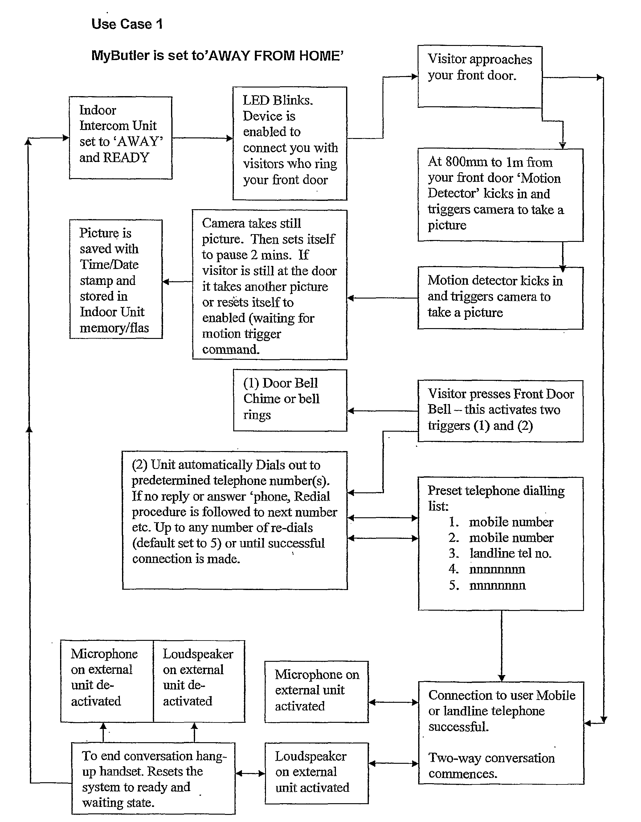
[0043]In a further subsidiary aspect, the said switch activates a camera. In this way a record may be maintained of all persons activating the switch, which may be of use later in identifying persons who may have undertaken unauthorised or illegal acts in or around the premises concerned.
[0045]In a further subsidiary aspect, said camera is activated by an automatic mechanism prior to the activation of the switch. This enables pictures to be taken of persons as they approach a door or an entrance even if they do not activate the manually activated switch.
[0047]In a further subsidiary aspect, said camera is activated by a separate proximity detector. The use of such proximity detectors enables the device to photograph intruders or visitors in the general area around the remote unit, for instance if the remote unit is mounted on a building entrance the camera may be able to photograph intruders in gardens or walkways immediately surrounding the building entrance by the use of remote proximity detectors.
[0050]In a further subsidiary aspect, activation of said base unit or said camera activates lighting means to illuminate selected areas. The activation of lighting means, which illuminates selected areas, enables the camera to take superior quality images at night than would otherwise be possible and additionally helps to generally deter intruders.

Problems solved by technology

The problem with this type of system is that in the event that the pressing of the button is not answered, the person seeking to gain access to the building, who may be a burglar or the like, may be alerted to the fact that the relevant premises are unoccupied.
The problem with this type of system is that such systems utilise broadband technology or alternatively radio communication and rely on the camera images being monitored, or at least recorded, 24 hours a day.
Such systems are therefore expensive to install, monitor and maintain.

Method used


Image

  • Security device comprising a plurality of interfaces
  • Security device comprising a plurality of interfaces
  • Security device comprising a plurality of interfaces

Examples


Embodiment Construction

)

[0060]The present invention comprises a remote unit and a base unit as described herein.

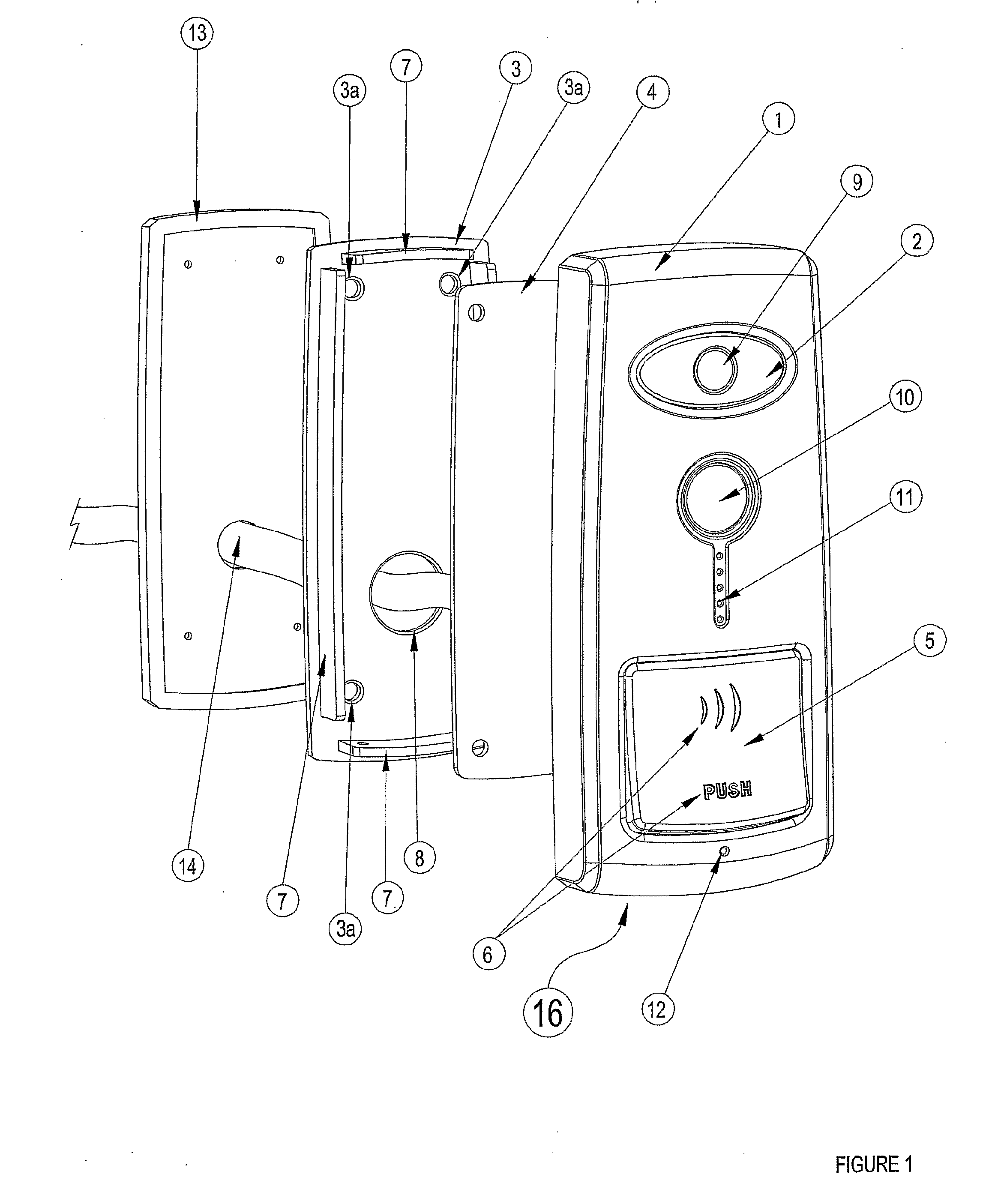
[0061]Reference is initially made to FIG. 1 of the drawings which shows a partially exploded perspective view of a remote unit according to the present invention as generally indicated by (16). The remote unit comprises four separate basic components, which are shown in FIG. 1 these comprise a steel chassis (3), a circuit board (4) (which also functions as a sub-frame), a plastic moulding (1) and a seal 13.

[0062]Appropriate holes (3a) are provided in the steel chassis (3), to enable the steel chassis (3) to be mounted to a door frame or a suitable surface (such that the device may be used as an entrance monitoring device) by the use of screws (not shown), three of the four holes (3a) provided are shown on FIG. 1.

[0063]An orifice (8) is also provided in the steel chassis (3) to allow the passage of cables (14) through the chassis (3). Said cables may be used to connect the remote unit to the base...


PUM


Abstract

A security device comprising interfacing means incorporating a speaker (50) and a microphone (49) for interfacing with a person; a mobile network transmitter; an internet communication means; a controller which automatically responds to interaction with said interfacing means and firstly employs said mobile network transmitter to dial one or more predetermined phone numbers through a mobile network for directly establishing a two way communication across the mobile network; wherein said controller secondly employs said internet communication means for transmission through the internet of data captured by said interfacing means.

Description

FIELD OF THE INVENTION[0001]The present invention relates to security devices and in particular to security devices for use at the entrances to buildings.PRIOR ART KNOWN TO THE APPLICANT[0002]Intercom units are commonly used as security devices to control the entrance of people to buildings such as flats, offices, homes or similar premises. A person seeking to gain entrance to the building presses a button such that a buzzer rings in the relevant premises. An occupant in the building uses the intercom to determine whether to allow access to the building to the person by releasing an electronic lock on the main entrance door to the building. Such systems may additionally incorporate the use of cameras to allow the occupant of the premises to see the person at the entrance. The problem with this type of system is that in the event that the pressing of the button is not answered, the person seeking to gain access to the building, who may be a burglar or the like, may be alerted to the ...

Claims


Application Information

Patent Timeline
IPC IPC(8): G08B21/00H04W4/90
CPCG08B13/19658G08B25/016G08B25/08H04L41/0604G10L15/26H04M11/025H04N7/186H04W4/22G08B25/008H04L41/0627H04W4/90
Inventor HAYWOOD, HELEN THERESA
Owner HAYWOOD HELEN THERESA
Learn More